Concept explainers
Videos
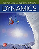
(a)
The acceleration of the panel and the tension in the cord after the system released from rest.
Answer to Problem 12.29P
Acceleration of the panel
Tension in the cord
Explanation of Solution
Given information:
Weight of panel
Weight of the counterweight
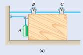
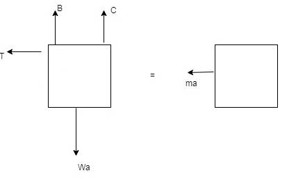
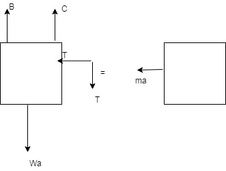
First, we draw the free body diagram and kinetic diagram of the panel:
F = force exerted by counterweight
Weight
Now, force
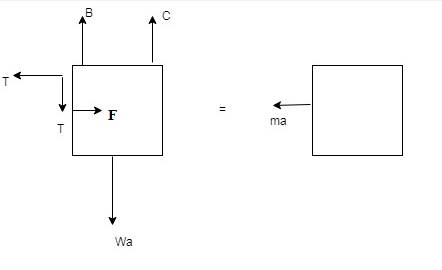
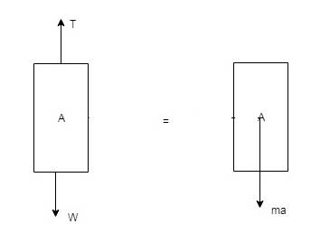
Now, computing the forces for counterweight A,
For this we draw the free body and kinetic diagram of the counterweight A;
Hence, from the above diagram it is clear that the acceleration component of counterweight A has two components.
Now,
Now, adding equation (1), (2) and (3);
Now, Tension in the cord from equation (3),
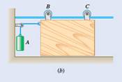
(b)
The acceleration of the panel and the tension in the cord after the system released from rest.
Answer to Problem 12.29P
Acceleration of the panel
Tension in the cord
Explanation of Solution
Given information:
Weight of panel
Weight of the counterweight
First, we draw the free body diagram and kinetic diagram of the panel:
F = force exerted by counterweight.
Weight
Now, force
Now, computing the forces for counterweight A,
For this we draw the free body and kinetic diagram of the counterweight A;
Now, adding equation (1) and (2);
Now, Tension in the cord from equation (1),
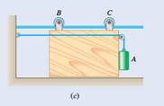
(c)
The acceleration of the panel and the tension in the cord after the system released from rest.
Answer to Problem 12.29P
Acceleration of the panel
Tension in the cord
Explanation of Solution
Given information:
Weight of panel
Weight of the counterweight
First, we draw the free body diagram and kinetic diagram of the panel:
F = force exerted by counterweight
Weight
Now, force
Since, panel is accelerated to the left, there is no force exerted by the panel on counterweight hence;
Now, computing the forces for counterweight A,
For this, we draw the free body and kinetic diagram of the counterweight A;

Now, adding equation (1) and (2);
Now, Tension in the cord from equation (1),
Want to see more full solutions like this?
Chapter 12 Solutions
Package: Vector Mechanics For Engineers: Dynamics With 1 Semester Connect Access Card


- Boxes A and B are at rest on a conveyor belt that is initially at rest. The belt is suddenly started in an upward direction so that slipping occurs between the belt and the boxes. Knowing that the coefficients of kinetic friction between the belt and the boxes are (μk) A= 0.30 and (μk)B= 0.32, determine the initial acceleration of each box.arrow_forwardA 500-lb crate B is suspended from a cable attached to a 40-lb trolley A which rides on an inclined I-beam as shown. Knowing that at the instant shown the trolley has an acceleration of 1.2 ft/s2 up and to the right, determine (a) the acceleration of B relative to A, (b) the tension in cable CD.arrow_forwardThe 1.2-lb flyballs of a centrifugal governor revolve at a constant speed v in the horizontal circle of 6-in. radius shown. Neglecting the weights of links AB, BC, AD, and DE and requiring that the links support only tensile forces, determine the range of the allowable values of v so that the magnitudes of the forces in the links do not exceed 17 lb.arrow_forward
- A spring scale A and a lever scale B having equal lever arms are fastened to the roof of an elevator, and identical packages are attached to the scales as shown. Knowing that when the elevator moves downward with an acceleration of 1 m/s2 the spring scale indicates a load of 60 N, determine (b) the load indicated by the spring scale and the mass needed to balance the lever scale when the elevator moves upward with an acceleration of 1 m/s2.arrow_forwardA force P with a magnitude of 3 N is applied to a tape wrapped around the body indicated. Knowing that the body rests on a frictionless horizontal surface, determine the acceleration of (a) point A, (b) point B.arrow_forwardHelp!!!!! A 500-lb box B is suspended from a cable attached to a 40-lb truck A mounted on an I-beam inclined in the form that shows. If at the indicated time the truck accelerates 1.2 ft / s2 up and to the right, determine (a) the acceleration of B in relation to A and b) the tension in the CD cable.arrow_forward
- The two blocks shown are originally at rest. Neglecting the masses of the pulleys and the effect of friction in the pulleys and between block A and the incline, determine (a) the acceleration of each block, (b) the tension in the cable.arrow_forward1 A 6-ft board is placed in a truck with one end resting against a block secured to the floor and the other leaning against a vertical partition. Draw the FBD and KD necessary to determine the maximum allowable acceleration of the truck if the board is to remain in the position shown.arrow_forwardThe 15-kg block B is supported by the 25-kg block A and is attached to a cord to which a 225-N horizontal force is applied as shown. Neglecting friction, determine (a) the acceleration of block A, (b) the acceleration of block B relative to A.arrow_forward
- A 7.5-lb collar is released from rest in the position shown, slides down the inclined rod, and compresses the spring. The direction of motion is reversed and the collar slides up the rod. Knowing that the maximum deflection of the spring is 5 in., determine (a) the coefficient of kinetic friction between the collar and the rod, (b) the maximum speed of the collar.arrow_forwardPin B has a mass m and slides along the slot in the rotating arm Oc and along the slot DE which is cut in a fixed horizontal plate. Neglecting friction and knowing that rod OC rotates at the constant rate 00. draw a FBD and KD that can be used to determine the forces P and Q exerted on pin B by rod OC and the wall of slot DE , respectively.arrow_forwardThe follower is attached to the end of a light telescopic rod that is pivoted at O. The follower is pressed against a frictionless spiral surface by a spring of stiffness and the free length . The equation of spiral, which lies in the horizontal plane, is , where and in radians. Immediately after the rod is released from rest in position OA, determine (a) the angular acceleration of the rod; and (b) the contact force between the follower and the spiral surface.arrow_forward
 Elements Of ElectromagneticsMechanical EngineeringISBN:9780190698614Author:Sadiku, Matthew N. O.Publisher:Oxford University Press
 Mechanics of Materials (10th Edition)Mechanical EngineeringISBN:9780134319650Author:Russell C. HibbelerPublisher:PEARSON
 Thermodynamics: An Engineering ApproachMechanical EngineeringISBN:9781259822674Author:Yunus A. Cengel Dr., Michael A. BolesPublisher:McGraw-Hill Education
 Control Systems EngineeringMechanical EngineeringISBN:9781118170519Author:Norman S. NisePublisher:WILEY
 Mechanics of Materials (MindTap Course List)Mechanical EngineeringISBN:9781337093347Author:Barry J. Goodno, James M. GerePublisher:Cengage Learning
 Engineering Mechanics: StaticsMechanical EngineeringISBN:9781118807330Author:James L. Meriam, L. G. Kraige, J. N. BoltonPublisher:WILEY