Statics and Mechanics of Materials (5th Edition)
5th Edition
ISBN: 9780134382869
Author: HIBBELER
Publisher: PEARSON
expand_more
expand_more
format_list_bulleted
Videos
Textbook Question
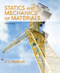
Chapter 12.3, Problem 45P
The member consists of two plastic channel strips 0.5 in. thick, glued together at A and B. If the distributed load has a maximum intensity of w0 = 3 kip/ft, determine the maximum shear stress resisted by the glue.
Expert Solution & Answer
Want to see the full answer?
Check out a sample textbook solution
Students have asked these similar questions
The member consists of two plastic channel strips 0.5 in. thick, glued together at A and B. If the glue can support an allowable shear stress of tallow= 600 psi, determine the maximum intensity w0 of the triangular distributed loading that can be applied to the member based on the strength of the glue.
If the load has a weight of 600 lb, determine the maximum normal stress on the cross section of the supporting member at section a–a. Also, plot the normalstress distribution over the cross section.
The strut is glued to the horizontal member at surface AB. If the strut has a thickness of 25 mm and the glue can withstand an average shear stress of 600 kPa, determine the maximum force P that can be applied to the strut.
Chapter 12 Solutions
Statics and Mechanics of Materials (5th Edition)
Ch. 12.2 - In each case, calculate the value of Q and t that...Ch. 12.2 - If the beam is subjected to a shear force of V =...Ch. 12.2 - Prob. 2FPCh. 12.2 - Determine the absolute maximum shear stress in the...Ch. 12.2 - If the beam is subjected to a shear force of V =...Ch. 12.2 - If the beam is made from four plates and subjected...Ch. 12.2 - If the wide-flange beam is subjected to a shear of...Ch. 12.2 - If the wide-flange beam is subjected to a shear of...Ch. 12.2 - If the wide-flange beam is subjected to a shear of...Ch. 12.2 - If the beam is subjected to a shear of V = 30kN,...
Ch. 12.2 - If the wide-flange beam is subjected to a shear of...Ch. 12.2 - The wood beam has an allowable shear stress of...Ch. 12.2 - The shaft is supported by a thrust bearing at A...Ch. 12.2 - The shaft is supported by a thrust bearing at A...Ch. 12.2 - Determine the largest shear force V that the...Ch. 12.2 - If the applied shear force V = 18 kip, determine...Ch. 12.2 - The overhang beam is subjected to the uniform...Ch. 12.2 - The beam is made from a polymer and is subjected...Ch. 12.2 - Determine the maximum shear stress in the strut if...Ch. 12.2 - Determine the maximum shear force V that the strut...Ch. 12.2 - Prob. 15PCh. 12.2 - Plot the shear-stress distribution over the cross...Ch. 12.2 - Prob. 17PCh. 12.2 - If the wide-flange beam is subjected to a shear of...Ch. 12.2 - If the wide-flange beam is subjected to a shear of...Ch. 12.2 - Determine the length of the cantilevered beam so...Ch. 12.2 - If the beam is made from wood having an allowable...Ch. 12.2 - Determine the largest intensity w of the...Ch. 12.2 - If w = 800 lb/ft, determine the absolute maximum...Ch. 12.2 - Determine the shear stress at point B on the web...Ch. 12.2 - Determine the maximum shear stress acting at...Ch. 12.2 - Railroad tics must be designed to resist large...Ch. 12.2 - Prob. 27PCh. 12.2 - Prob. 28PCh. 12.2 - Determine the maximum shear stress in the T-beam...Ch. 12.2 - Determine the maximum shear stress in the T-beam...Ch. 12.2 - Prob. 31PCh. 12.3 - The two identical boards are bolted together to...Ch. 12.3 - Two identical 20-mm-thick plates are bolted to the...Ch. 12.3 - Prob. 8FPCh. 12.3 - Prob. 9FPCh. 12.3 - The beam is constructed from two boards fastened...Ch. 12.3 - The beam is constructed from two boards fastened...Ch. 12.3 - The beam is constructed from three boards. If it...Ch. 12.3 - The beam is constructed from three boards....Ch. 12.3 - Prob. 36PCh. 12.3 - The double T-beam is fabricated by welding the...Ch. 12.3 - The beam is constructed from three boards....Ch. 12.3 - A beam is constructed from three boards bolted...Ch. 12.3 - The simply supported beam is built up from three...Ch. 12.3 - Prob. 41PCh. 12.3 - Prob. 42PCh. 12.3 - Prob. 43PCh. 12.3 - The box beam is constructed from four boards that...Ch. 12.3 - The member consists of two plastic channel strips...Ch. 12.3 - The member consists of two plastic channel strips...Ch. 12.3 - Prob. 47PCh. 12.3 - Prob. 48PCh. 12 - The beam is fabricated from four boards nailed...Ch. 12 - Prob. 2RPCh. 12 - Prob. 3RPCh. 12 - Prob. 4RPCh. 12 - Prob. 5RPCh. 12 - Prob. 6RPCh. 12 - Prob. 7RPCh. 12 - The member consists of two triangular plastic...Ch. 12 - If the pipe is subjected to a shear of V = 15 kip,...
Knowledge Booster


Learn more about
Need a deep-dive on the concept behind this application? Look no further. Learn more about this topic, mechanical-engineering and related others by exploring similar questions and additional content below.Similar questions
- The box beam is constructed from four boards that are fastened together using nails spaced along the beam every 2 in. If each nail can resist a shear force of 50 lb, determine the largest force P that can be applied to the beam without causing failure of the nails.arrow_forwardDetermine the largest intensity w of the distributed load that the member can support if the allowable shear stress is tallow = 800 psi. The supports at A and B are smooth.arrow_forwardThe assembly consists of two sections of galvanized steel pipe connected together using a reducing coupling at B. The smaller pipe has an outer diameter of 0.75 in. and an inner diameter of 0.68 in., whereas the larger pipe has an outer diameter of 1 in. and an inner diameter of 0.86 in. If the pipe istightly secured to the wall at C, determine the maximum shear stress in each section of the pipe when the couple is applied to the handles of the wrench.arrow_forward
- The beam is constructed from three plastic strips. If the glue can support a shear stress of tallow = 8 kPa, determine the largest magnitude of the loads P that the beam can support.arrow_forwardThe plastic block is subjected to an axial compressive force of 600 N. Assuming that the caps at the top and bottom distribute the load uniformly throughout the block, determine the average normal and average shear stress acting along section a–a.arrow_forwardThe pier is made of a material having a specific weight g. If it has a square cross-section, determine its width w as a function of z so that the average normal stress in the pier remains constant. The pier supports a constant load P at its top where its width is w1.arrow_forward
- The rigid beam is supported at its ends by two A-36 steel tie rods. The rods have diameters dAB = 0.5 in. and dCD = 0.3 in. If the allowable stress for the steel is sallow = 16.2 ksi, determine the largest intensity of the distributed load w and its length x on the beam so that the beam remains in the horizontal position when it is loaded.arrow_forwardDetermine the maximum shear stress in the strut if it is subjected to a shear force of V = 20 kN.arrow_forwardThe pin is used to connect the three links together. Due to wear, the load is distributed over the top and bottom of the pin as shown on the free-body diagram. If the diameter of the pin is 0.40 in., determine the maximum bending stress on the cross-sectional area at the center section a–a. For the solution it is first necessary to determine the load intensities w1 and w2.arrow_forward
- ‘The frame supports the loading shown. The pin at A has a diameter of 0.25 in. If it is subjected to double shear, determine the average shear stress in the pin.arrow_forwardThe double T-beam is fabricated by welding the three plates together as shown. If the weld can resist a shear stress tallow = 90 MPa, determine the maximum shear V that can be applied to the beam.arrow_forwardThe elbow of the pipe has an outer radius of 0.75 in. and an inner radius of 0.63 in. If the assembly is subjected to the moments of M = 25 lb # in., determine the maximum stress at section a–a.arrow_forward
arrow_back_ios
SEE MORE QUESTIONS
arrow_forward_ios
Recommended textbooks for you
 Elements Of ElectromagneticsMechanical EngineeringISBN:9780190698614Author:Sadiku, Matthew N. O.Publisher:Oxford University Press
 Mechanics of Materials (10th Edition)Mechanical EngineeringISBN:9780134319650Author:Russell C. HibbelerPublisher:PEARSON
 Thermodynamics: An Engineering ApproachMechanical EngineeringISBN:9781259822674Author:Yunus A. Cengel Dr., Michael A. BolesPublisher:McGraw-Hill Education
 Control Systems EngineeringMechanical EngineeringISBN:9781118170519Author:Norman S. NisePublisher:WILEY
 Mechanics of Materials (MindTap Course List)Mechanical EngineeringISBN:9781337093347Author:Barry J. Goodno, James M. GerePublisher:Cengage Learning
 Engineering Mechanics: StaticsMechanical EngineeringISBN:9781118807330Author:James L. Meriam, L. G. Kraige, J. N. BoltonPublisher:WILEY
Elements Of Electromagnetics
Mechanical Engineering
ISBN:9780190698614
Author:Sadiku, Matthew N. O.
Publisher:Oxford University Press
Mechanics of Materials (10th Edition)
Mechanical Engineering
ISBN:9780134319650
Author:Russell C. Hibbeler
Publisher:PEARSON
Thermodynamics: An Engineering Approach
Mechanical Engineering
ISBN:9781259822674
Author:Yunus A. Cengel Dr., Michael A. Boles
Publisher:McGraw-Hill Education
Control Systems Engineering
Mechanical Engineering
ISBN:9781118170519
Author:Norman S. Nise
Publisher:WILEY
Mechanics of Materials (MindTap Course List)
Mechanical Engineering
ISBN:9781337093347
Author:Barry J. Goodno, James M. Gere
Publisher:Cengage Learning
Engineering Mechanics: Statics
Mechanical Engineering
ISBN:9781118807330
Author:James L. Meriam, L. G. Kraige, J. N. Bolton
Publisher:WILEY
Differences between Temporary Joining and Permanent Joining.; Author: Academic Gain Tutorials;https://www.youtube.com/watch?v=PTr8QZhgXyg;License: Standard Youtube License