
Videos
An adiabatic 0.2-m3 storage tank that is initially evacuated is connected to a supply line that carries nitrogen at 225 K and 10 MPa. A valve is opened, and nitrogen flows into the tank from the supply line. The valve is closed when the pressure in the tank reaches 10 MPa. Determine the final temperature in the tank (a) treating nitrogen as an ideal gas, and (b) using generalized charts. Compare your results to the actual value of 293 K.
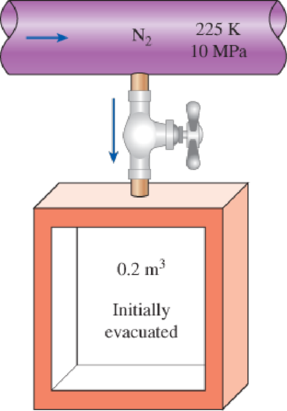
FIGURE P12–101
(a)
The final temperature in the tank by treating nitrogen as an ideal gas and compare the result to the actual value of
Answer to Problem 101RP
The final temperature in the tank by treating nitrogen as an ideal gas is
Explanation of Solution
Write the equation of mass balance.
Here, the inlet mass is
The change in mass of the system for the control volume is expressed as,
Here, the suffixes 1 and 2 indicates the initial and final states of the system.
Consider the given insulated tank as the control volume.
The valve is closed when the pressure in tank reaches to
Rewrite the Equation (I) as follows.
Write the energy balance equation.
Here, the heat transfer is
Since the tank is adiabatic, there is no heat transfer i.e.
The Equation (III) reduced as follows.
Substitute
Express the Equation (V) in molar basis.
Here, the molar mass of nitrogen is
Conclusion:
The inlet condition of the nitrogen is
While considering the nitrogen as the ideal gas, its enthalpy is solely depends on temperature.
Refer Table A-18, “Ideal-gas properties of nitrogen,
The molar enthalpy of nitrogen corresponding to the temperature of
Refer Equation (VI).
The final temperature of the nitrogen is expressed as follows.
Refer Table A-18, “Ideal-gas properties of nitrogen,
The final temperature
Thus, the final temperature in the tank by treating nitrogen as an ideal gas is
The percentage error with the actual temperature value of
The error associated is
(b)
The final temperature in the tank by using generalized departure charts.
Answer to Problem 101RP
The final temperature in the tank by using generalized departure charts is
Explanation of Solution
Refer Table A-1, “Molar mass, gas constant, and critical-point properties”.
The critical temperature and pressure of nitrogen gas is as follows.
The reduced pressure
At inlet:
Refer Figure A-29, “Generalized enthalpy departure chart”.
The enthalpy departure factor
Write formula for enthalpy departure factor
Here, the inlet molar enthalpy at ideal gas state is
Rearrange the Equation (I) to obtain
Write the formula for molar enthalpy at final state
Write the formula for molar internal energy at final state.
Here, the compressibility factor is
The universal gas constant
Conclusion:
Refer part (a) answer for
Substitute
Refer Equation (VI).
It is given that the actual final temperature of nitrogen is
Consider the exit temperature
The reduced pressure
Refer Figure A-29, “Generalized enthalpy departure chart”.
The enthalpy departure factor
Refer Figure A-15, “Nelson–Obert generalized compressibility chart”.
The compressibility factor
Refer Table A-18, “Ideal-gas properties of nitrogen,
The final molar enthalpy of nitrogen
Substitute
Substitute
Express interpolation formula to determine the final temperature
Substitute
Thus, the final temperature in the tank by using generalized departure charts is
The percentage error with the actual temperature value of
The error associated is
Want to see more full solutions like this?
Chapter 12 Solutions
CENGEL'S 9TH EDITION OF THERMODYNAMICS:


- a reciprocating compressor 0.1 m3 of air at 0.95 bar and 32°C is compressed according to PVn =constant until the pressure is 7 bar. Determine the volume and temperature of the air after compression. The work done on the air and the heat rejected to the cylinder walls assuming the compressor is water cooled and n=1.1 show the cancellation of units and formula usedarrow_forwardPlease include all steps and assumptionsarrow_forward(b) A rigid tank of 10 L vessel initially contains a mixture of liquid water and vapor at 100°C with 12.3% quality. Heat of 100 kJ is supplied to the rigid tank until the water reach superheated level at 1 MPa. The maximum temperature that the rigid tank can withstand is of 300°C. Evaluate if the rigid tank is able to withstand the heat supply of 100 kJ. Justify your answer with related calculation.arrow_forward
- 3) In a fixed volume container with a volume of 0.1 m^3, initially there is saturated water vapor at 130°C. The vessel is connected to a pipe through which steam flows through a valve at 2 MPa pressure and 350°C temperature. Then the valve opens and steam enters the container. Meanwhile, the temperature of the steam in the container remains constant at 130°C due to the heat transfer to the environment. When it is observed that 3/4 of the water in the container covers the liquid phase by mass, the valve is closed. Calculate a) the final pressure in the container, b) the mass of steam entering the container, c) the heat transfer to the environment.arrow_forwardFind the dryness fraction of a steam having a specific volume of 15 m3 /kg after expansion in a turbine. The specific volumes of saturated liquid and saturated vapor corresponding to the pressure are 0.001 m3 /kg and 15.25 m3 /kg, respectively.arrow_forwardAn insulated evacuated tank of 1.75-m> volume is attached to a line containing steam at 400 Wa and 513.15 K (240°C). Steam flows into the tank until the pressure in the tank reaches 400 kPa. Assuming no heat flow from the steam to the tank, prepare graphs showing the mass of steam in the tank and its temperature as a function of pressure in the tankarrow_forward
- A and B containers (fixed volume) are connected together by a valve. Tank A contains 400 kPa and 0.3 m3 refrigerant 134a at 60% dryness. Tank B contains 0.5 m3 of refrigerant 134a at 240 kPa pressure and 100 oC temperature. Then the valve is opened and the system reaches 280 kPa equilibrium pressure. Calculate the final temperature.arrow_forwardThe internal energy of a certain ideal gas is given by the expression U=850 + 0.529pv Btu/lb Where p is in psia. Determine the exponent k in PVK=C for the gas undergoing an isentropic processarrow_forwardIn the first case, there is 5 kg of water at 300 kPa (3 bar) pressure and 60% dryness in a closed container whose volume does not change. Heat transfer is performed until the closed container water reaches a pressure value of 1 MPa. The limit temperature of the closed container is 300 Cwill be taken.Note: Changes in kinetic and potential energies are negligible.(P0 = 100 kPa, T0 = 25 ◦C and T (K) = 273.15 + ◦C)a) Find the heat transfer to the sealed container.b) Find the exergy that disappears during the process.arrow_forward
- Consider the steam engine shown in the figure below which is composed of a boiler and an insulated turbine. The boiler is a rigid tank with a volume of 50 L and initially contains saturated liquid vapor mixture of H₂0 at 125 kPa with a quality of 0.04. Now, H₂O in the boiler is heated. When the pressure in the boiler reaches 800 kPa, the pressure regulator opens and allows the saturated vapor to enter the turbine at a pressure of 800 kPa. Heating continues until all H₂O remaining in the boiler is saturated vapor. If the exit from the turbine is a saturated vapor at 125 kPa, determine (a) the total heat transfer to the boiler and (b) the total turbine work. Show the process path of H₂O in the boiler on P-v and T-v diagrams. ↑ Vapor H₂O Liquid H₂O Boiler Pressure regulator Insulated turbinearrow_forwarduse T(c)= 125arrow_forwardAir at 20°C and 7 bar is contained in a rigid tank of 0.57 m3 volume capacity. The tank is provided with a valve that opens at a pressure of 8.5 bar and remains open until the pressure drops to 8.15 bar. Determine: (a) Air temperature just before the valve opens (b) Mass of air lost due to fire. Assuming: A fire occurs and causes the valve to open and the temperature of the air remains constant during discharge and air in the tank behaves as an ideal gas.arrow_forward
 Elements Of ElectromagneticsMechanical EngineeringISBN:9780190698614Author:Sadiku, Matthew N. O.Publisher:Oxford University Press
 Mechanics of Materials (10th Edition)Mechanical EngineeringISBN:9780134319650Author:Russell C. HibbelerPublisher:PEARSON
 Thermodynamics: An Engineering ApproachMechanical EngineeringISBN:9781259822674Author:Yunus A. Cengel Dr., Michael A. BolesPublisher:McGraw-Hill Education
 Control Systems EngineeringMechanical EngineeringISBN:9781118170519Author:Norman S. NisePublisher:WILEY
 Mechanics of Materials (MindTap Course List)Mechanical EngineeringISBN:9781337093347Author:Barry J. Goodno, James M. GerePublisher:Cengage Learning
 Engineering Mechanics: StaticsMechanical EngineeringISBN:9781118807330Author:James L. Meriam, L. G. Kraige, J. N. BoltonPublisher:WILEY