
Concept explainers
Videos
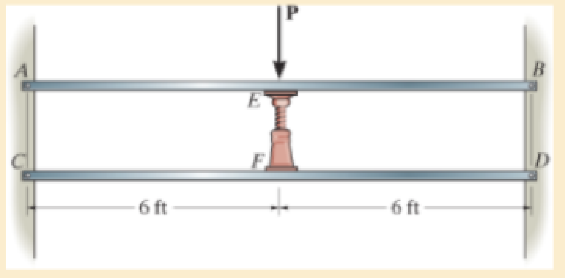
Each of the two members is made from 6061-T6 aluminum and has a square cross section 1 in. × 1 in. They are pin connected at their ends and a jack is placed between them and opened until the force it exerts on each member is 50 lb. Determine the greatest force P that can be applied to the center of the top member without causing either of the two members to yield. For the analysis neglect the axial force in each member. Assume the jack is rigid.
Prob. 12–128
Want to see the full answer?
Check out a sample textbook solution
Chapter 12 Solutions
MECHANICS OF MATERIAL IN SI UNITS
Additional Engineering Textbook Solutions
Automotive Technology: Principles, Diagnosis, and Service (5th Edition)
DeGarmo's Materials and Processes in Manufacturing
Shigley's Mechanical Engineering Design (McGraw-Hill Series in Mechanical Engineering)
Automotive Technology: Principles, Diagnosis, And Service (6th Edition) (halderman Automotive Series)
HEAT+MASS TRANSFER:FUND.+APPL.
Mechanics of Materials, 7th Edition


- The bracket is held to the wall using three A-36 steel bolts at B, C, and D. Each bolt has a diameter of 0.5 in. and an unstretched length of 2 in. If a force of 800 lb is placed on the bracket as shown, determine how far, s, the top bracket at bolt D moves away from the wall. For the calculation, assume that the bolts carry no shear; rather, the vertical force of 800 lb is supported by the toe at A. Also, assume that the wall and bracket are rigid. A greatly exaggerated deformation of the bolts is shown.arrow_forwardDetermine the magnitude of the pin force at A. Assume W = 675 lb, a = 2.7 ft, b = 2.0 ft, r = 9 in. W Answer: A = Mo B D lbarrow_forwardFind the largest force P that can be applied to the column.arrow_forward
- A.The bar of negligible weight is supported by two springs, each having a stiffness k = 98 N/m. If the springs are originally unstretched, and the force is vertical as shown, determine the angle the bar makes with the horizontal, when the 31-N force is applied to the bar. B.Determine the stiffness k of each spring so that the 32-N force causes the bar to tip = 13.6° when the force is applied. Originally the bar is horizontal and the springs are unstretched. Neglect the weight of the bar.arrow_forwardThe torsional spring at B is undeformed when bars OB and BD are both in the vertical position and overlap. If a force F is required to position the bars at a steady orientation θ = 64°, determine the torsional spring stiffness kT. The slot at C is smooth, and the weight of the bars is negligible. In this configuration, the pin at C is positioned at the midpoint of the slotted bar.arrow_forwardDetermine the magnitude of the pin force at A. Assume W = 645 lb, a = 4.5 ft, b = 3.3 ft, r = 8 in. B W Answer: A = Ibarrow_forward
- Determine the tensile force of the rope.arrow_forwardThe 41-lbrectangular access door is held in the 90° open position by the single prop CD. Determine the force Fin the prop and the magnitude of the force normal to the hinge axis AB in each of the small hinges A and B. Assume a= 22 in., b= 36 in., c- 13 in., d= 49 in. Answers: F= Ib A- Ib B- Ibarrow_forwardThe hoist consists of a single rope and an arrangement of frictionless pulleys as shown. If the angle 0 = 33°, determine the force that must be applied to the rope, Frope, to lift a load of 4.7 kN. The three- pulley and hook assembly at the center of the system has a mass of 28.5 kg with a center of mass that lies on the line of action of the force applied to the hook. cc 130 BY NC SA 2013 Michael Swanbom Note the figure may not be to scale. Frope KN B A Fhook Fropearrow_forward
- The rigid link is supported by a pin at A and two A-36 steel wires, each having an unstretched length of 12 in. and cross-sectional area of 0.0125 in2. Determine the force developed in the wires when the link supports the vertical load of 350 lb.arrow_forwardMembers AC and AB support the 300-lb crate. Determine the tensile force developed in each member?arrow_forwardDetermine the resulting internal loads on the cross section through point C in the grippers. It has a pin at A and the jaws at B are smooth. *The develop free-body diagrams. *Apply the equations of static equilibrium. 20 N -120 mm- - 40 mm 15 mm C 80 mm 30° 20 Narrow_forward
 Elements Of ElectromagneticsMechanical EngineeringISBN:9780190698614Author:Sadiku, Matthew N. O.Publisher:Oxford University Press
 Mechanics of Materials (10th Edition)Mechanical EngineeringISBN:9780134319650Author:Russell C. HibbelerPublisher:PEARSON
 Thermodynamics: An Engineering ApproachMechanical EngineeringISBN:9781259822674Author:Yunus A. Cengel Dr., Michael A. BolesPublisher:McGraw-Hill Education
 Control Systems EngineeringMechanical EngineeringISBN:9781118170519Author:Norman S. NisePublisher:WILEY
 Mechanics of Materials (MindTap Course List)Mechanical EngineeringISBN:9781337093347Author:Barry J. Goodno, James M. GerePublisher:Cengage Learning
 Engineering Mechanics: StaticsMechanical EngineeringISBN:9781118807330Author:James L. Meriam, L. G. Kraige, J. N. BoltonPublisher:WILEY