
Concept explainers
Videos
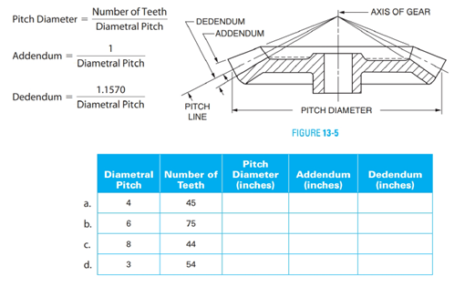
A cross-sectional view of a bevel gear is shown in Figure 13-5. Given the diametral pitch and the number of gear teeth, determine the pitch diameter, the addendum, and thededendum. Round the answers to 4 decimal places.
(a)
The pitch diameter, addendum and dedendum of the gear.
Answer to Problem 12A
Explanation of Solution
Given:
Diametral pitch
Number of teeth
Calculation:
The pitch diameter is calculated by the formula
Addendum is calculated by the formula
And, dedendum is calculated by the formula
Conclusion:
The pitch diameter, addendum and dedendum of gear are
(b)
The pitch diameter, addendum and dedendum of the gear.
Answer to Problem 12A
Explanation of Solution
Given:
Diametral pitch
Number of teeth
Calculation:
The pitch diameter is calculated by the formula
Addendum is calculated by the formula
And, dedendum is calculated by the formula
Conclusion:
The pitch diameter, addendum and dedendum of gear are
(c)
The pitch diameter, addendum and dedendum of the gear.
Answer to Problem 12A
Explanation of Solution
Given:
Diametral pitch
Number of teeth
Calculation:
The pitch diameter is calculated by the formula
Addendum is calculated by the formula
And, dedendum is calculated by the formula
Conclusion:
The pitch diameter, addendum and dedendum of gear are
(d)
The pitch diameter, addendum and dedendum of the gear.
Answer to Problem 12A
Explanation of Solution
Given:
Diametral pitch
Number of teeth
Calculation:
The pitch diameter is calculated by the formula
Addendum is calculated by the formula
And, dedendum is calculated by the formula
Conclusion:
The pitch diameter, addendum and dedendum of gear are
Want to see more full solutions like this?
Chapter 13 Solutions
Mathematics For Machine Technology


- Refer to the Decimal-Inch Spur Gears Table under the heading "Gearing-Diametral Pitch System" in Unit 48 to determine the pitch diameter of an 8-pitch gear that has 45 teeth.arrow_forwardMeasure the lengths of dimensions a-f in Figure 30-25 to the nearer whole millimeter.arrow_forwardAll sections of the block in Figure 13-9 are equal in length. Determine the length A to the nearest thousandth millimeter.arrow_forward
- Refer to the shaft shown in Figure 6-4. Determine the missing dimensions in the table using the dimensions given. All dimensions are in inches.arrow_forwardMeasure the lengths of g-k in Figure 30-26 to the nearer whole millimeter.arrow_forwardFind the decimal value of the distance C in Figure 10-3. Note the total unit value of the line.arrow_forward
- Find the metal area of the washer in Figure 29-6. Round the answer to the nearest tenth.arrow_forwardA section of a piece of round stock with a V-groove cut is shown. Find the sectional area of the stock. Round the answer to the nearest square millimeter.arrow_forwardThe central angle corresponding to a circular brake shoe measures 60. To two decimal places how long is the curved surface of the brake shoe if the length of the radius is 7 in.arrow_forward
- The distance between the centers of two holes can be checked with a vernier caliper. The position of the caliper in measuring the inside distance between two holes is shown in Figure 29-10. To determine the setting on the caliper, subtract the radius of each hole (one-half the diameter) from the center distance. In Exercises 19 through 23, give the hole diameters and the distances between centers. For each, determine (1) the main scale setting and (2) the vernier scale setting. All dimensions are in inches.arrow_forwardThe distance between the centers of two holes can be checked with a vernier caliper. The position of the caliper in measuring the inside distance between two holes is shown in Figure 29-10. To determine the setting on the caliper, subtract the radius of each hole (one-half the diameter) from the center distance. In Exercises 19 through 23, give the hole diameters and the distances between centers. For each, determine (1) the main scale setting and (2) the vernier scale setting. All dimensions are in inches 23. Note: Hole tolerances and center distance tolerances are shown. Maximum and minimum vernier scale settings are required.arrow_forwardThe length, L, of the point on any standard 118° included angle drill, as shown in Figure 12-5, can be calculated using the formula L=0.3 O where represents the diameter of the drill. Determine the lengths of the following drill points with the given diameters. Round to 3 decimal places for inches and 1 decimal place for millimeters. a. 12 b. 14 c. 38 d. 10 mm e. 25 mm f. 45 mmarrow_forward
- Mathematics For Machine TechnologyAdvanced MathISBN:9781337798310Author:Peterson, John.Publisher:Cengage Learning,
 Elementary Geometry for College StudentsGeometryISBN:9781285195698Author:Daniel C. Alexander, Geralyn M. KoeberleinPublisher:Cengage Learning
 Algebra and Trigonometry (MindTap Course List)AlgebraISBN:9781305071742Author:James Stewart, Lothar Redlin, Saleem WatsonPublisher:Cengage Learning
  Elementary Geometry For College Students, 7eGeometryISBN:9781337614085Author:Alexander, Daniel C.; Koeberlein, Geralyn M.Publisher:Cengage,
 Trigonometry (MindTap Course List)TrigonometryISBN:9781305652224Author:Charles P. McKeague, Mark D. TurnerPublisher:Cengage Learning