
Applied Statics and Strength of Materials (6th Edition)
6th Edition
ISBN: 9780133840544
Author: George F. Limbrunner, Craig D'Allaird, Leonard Spiegel
Publisher: PEARSON
expand_more
expand_more
format_list_bulleted
Concept explainers
Videos
Textbook Question
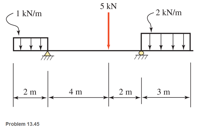
Chapter 13, Problem 13.45SP
Refer to the beam shown and draw complete shear and bending moment diagrams. Show ordinates at key points and indicate magnitude of shear and moment. Neglect the beam weight.
Expert Solution & Answer
Want to see the full answer?
Check out a sample textbook solution
Chapter 13 Solutions
Applied Statics and Strength of Materials (6th Edition)
Ch. 13 - through 13.6 Calculate the reactions at points A...Ch. 13 - Calculate the reactions at points A and B for the...Ch. 13 - through 13.6 Calculate the reactions at points A...Ch. 13 - Calculate the reactions at points A and B for the...Ch. 13 - Calculate the reactions at points A and B for the...Ch. 13 - Calculate the reactions at points A and B for the...Ch. 13 - Calculate the shear and bending moment at 4 m and...Ch. 13 - Calculate the shear and bending moment at 3 ft and...Ch. 13 - Calculate the shear and bending moment at midspan...Ch. 13 - Calculate the shear and bending moment at 5 ft and...
Ch. 13 - Calculate the shear and bending moment at 5 m and...Ch. 13 - For the beams shown, draw complete shear diagrams.Ch. 13 - For the beams shown, draw complete shear diagrams.Ch. 13 - Prob. 13.14PCh. 13 - For the beams shown, draw complete shear diagrams.Ch. 13 - For the beams shown (next page), draw complete...Ch. 13 - For the beams shown (next page), draw complete...Ch. 13 - For the beams shown (next page), draw complete...Ch. 13 - For the beams shown (next page), draw complete...Ch. 13 - For the beams shown (next page), draw complete...Ch. 13 - For the beams shown, draw complete shear and...Ch. 13 - For the beams shown, draw complete shear and...Ch. 13 - For the beams shown, draw complete shear and...Ch. 13 - A moving-load system is composed of two...Ch. 13 - A moving-load system is composed of two...Ch. 13 - One of the standard truck loads used in the design...Ch. 13 - Write a computer program that will calculate the...Ch. 13 - Write a program that will calculate the shear and...Ch. 13 - Viking Consultants wishes to generate a table of...Ch. 13 - Calculate the reactions for the simple beams...Ch. 13 - Calculate the reactions for the overhanging beams...Ch. 13 - Calculate the reactions at points A and B for the...Ch. 13 - Calculate the reactions at points A and B for the...Ch. 13 - For the beams of Problem 13.33, calculate the...Ch. 13 - For the beam shown, calculate the shear and...Ch. 13 - Calculate the shear and bending moment at points 4...Ch. 13 - Calculate the shear arid bending moment at points...Ch. 13 - Calculate the shear and bending moment at points...Ch. 13 - Refer to the beam shown and draw complete shear...Ch. 13 - Refer to the beam shown and draw complete shear...Ch. 13 - Refer to the beam shown and draw complete shear...Ch. 13 - Refer to the beam shown and draw complete shear...Ch. 13 - Refer to the beam shown and draw complete shear...Ch. 13 - Refer to the beam shown and draw complete shear...Ch. 13 - Refer to the beam shown and draw complete shear...Ch. 13 - Refer to the beam shown and draw complete shear...Ch. 13 - Refer to the beam shown and draw complete shear...Ch. 13 - Refer to the indicated problem and draw complete...Ch. 13 - Refer to the indicated problem and draw complete...Ch. 13 - Refer to the indicated problem and draw complete...Ch. 13 - Refer to the indicated problem and draw complete...Ch. 13 - Refer to the indicated problem and draw complete...Ch. 13 - Refer to the indicated problem and draw complete...Ch. 13 - Refer to the indicated problem and draw complete...Ch. 13 - Refer to the indicated problem and draw complete...Ch. 13 - Refer to the indicated problem and draw complete...Ch. 13 - Refer to the indicated problem and draw complete...Ch. 13 - Refer to the indicated problem and draw complete...Ch. 13 - A two-axle roller with axles 5 m apart passes over...Ch. 13 - A moving load system with wheels at fixed...Ch. 13 - A moving-load system with wheels spaced as shown...
Knowledge Booster


Learn more about
Need a deep-dive on the concept behind this application? Look no further. Learn more about this topic, mechanical-engineering and related others by exploring similar questions and additional content below.Similar questions
- For the beam AB shown in Cases 1 and 2, derive and plot expressions for the shear force and bending moment acting on section 1 in terms of the distance x (0 < x< L). [Note: Case 1 results in the conventional V- and M-diagrams, in which the loads are fixed and the location of the section varies; the diagrams for Case 2 (called influence diagrams) show the variation of V and M at a fixed section as the location of the load is varied]arrow_forwardConstruct the shear force and bending moment diagrams for the beam shown by the area method. Neglect the weight of the beam.arrow_forward
Recommended textbooks for you
 International Edition---engineering Mechanics: St...Mechanical EngineeringISBN:9781305501607Author:Andrew Pytel And Jaan KiusalaasPublisher:CENGAGE L
International Edition---engineering Mechanics: St...
Mechanical Engineering
ISBN:9781305501607
Author:Andrew Pytel And Jaan Kiusalaas
Publisher:CENGAGE L
Understanding Shear Force and Bending Moment Diagrams; Author: The Efficient Engineer;https://www.youtube.com/watch?v=C-FEVzI8oe8;License: Standard YouTube License, CC-BY
Bending Stress; Author: moodlemech;https://www.youtube.com/watch?v=9QIqewkE6xM;License: Standard Youtube License