
Applied Statics and Strength of Materials (6th Edition)
6th Edition
ISBN: 9780133840544
Author: George F. Limbrunner, Craig D'Allaird, Leonard Spiegel
Publisher: PEARSON
expand_more
expand_more
format_list_bulleted
Concept explainers
Videos
Textbook Question
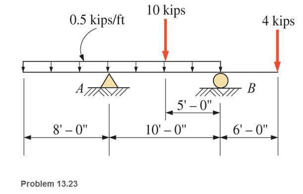
Chapter 13, Problem 13.23P
For the beams shown, draw complete shear and moment diagrams and state the values of the maximum positive and negative moments.
Expert Solution & Answer

Learn your wayIncludes step-by-step video

schedule10:25
Students have asked these similar questions
Draw the shear diagram for the beam. Follow the sign convention.
Draw the moment diagram for the beam. Follow the sign convention.
For the following beams shown,
(1) Derive the shear force and bending moment equations; and
(2) draw the shear force and bending moment diagrams. Neglect the weight of the beam.
Draw the simplified free-body diagram and below it the shear and bending moment diagrams.
Show all necessary solutions. Let the analysis be from left to right. Determine the points of zero
shear (if any), their distance from point A, and the bending moments at these points. Indicate the
value of all the points, degree of all curves, and the maximum shear and maximum bending
moment of the beam.
Use the method of sections. Beam ABCD has a hanger
connected at B and is supported by a roller at A and a pin
at C.
100 N
L1
This is not your own property so
do not use it in any way as if it
were your own.
M
L1= 206 N/m
L2 = 30 N/m
L3 = 214 N/m
°
L4 = 89 N/m
M = 89 N-m
A
Simplified of the
you to repro
3. Any rexodus
ers have Exploratory Distance
x=
L2
1.5 m
Shear (N)
D
This is not your own property so
do not use it in any way as if it
were your own.
2.5m
Bending Moment (N-m)
L4
с
L3
Chapter 13 Solutions
Applied Statics and Strength of Materials (6th Edition)
Ch. 13 - through 13.6 Calculate the reactions at points A...Ch. 13 - Calculate the reactions at points A and B for the...Ch. 13 - through 13.6 Calculate the reactions at points A...Ch. 13 - Calculate the reactions at points A and B for the...Ch. 13 - Calculate the reactions at points A and B for the...Ch. 13 - Calculate the reactions at points A and B for the...Ch. 13 - Calculate the shear and bending moment at 4 m and...Ch. 13 - Calculate the shear and bending moment at 3 ft and...Ch. 13 - Calculate the shear and bending moment at midspan...Ch. 13 - Calculate the shear and bending moment at 5 ft and...
Ch. 13 - Calculate the shear and bending moment at 5 m and...Ch. 13 - For the beams shown, draw complete shear diagrams.Ch. 13 - For the beams shown, draw complete shear diagrams.Ch. 13 - Prob. 13.14PCh. 13 - For the beams shown, draw complete shear diagrams.Ch. 13 - For the beams shown (next page), draw complete...Ch. 13 - For the beams shown (next page), draw complete...Ch. 13 - For the beams shown (next page), draw complete...Ch. 13 - For the beams shown (next page), draw complete...Ch. 13 - For the beams shown (next page), draw complete...Ch. 13 - For the beams shown, draw complete shear and...Ch. 13 - For the beams shown, draw complete shear and...Ch. 13 - For the beams shown, draw complete shear and...Ch. 13 - A moving-load system is composed of two...Ch. 13 - A moving-load system is composed of two...Ch. 13 - One of the standard truck loads used in the design...Ch. 13 - Write a computer program that will calculate the...Ch. 13 - Write a program that will calculate the shear and...Ch. 13 - Viking Consultants wishes to generate a table of...Ch. 13 - Calculate the reactions for the simple beams...Ch. 13 - Calculate the reactions for the overhanging beams...Ch. 13 - Calculate the reactions at points A and B for the...Ch. 13 - Calculate the reactions at points A and B for the...Ch. 13 - For the beams of Problem 13.33, calculate the...Ch. 13 - For the beam shown, calculate the shear and...Ch. 13 - Calculate the shear and bending moment at points 4...Ch. 13 - Calculate the shear arid bending moment at points...Ch. 13 - Calculate the shear and bending moment at points...Ch. 13 - Refer to the beam shown and draw complete shear...Ch. 13 - Refer to the beam shown and draw complete shear...Ch. 13 - Refer to the beam shown and draw complete shear...Ch. 13 - Refer to the beam shown and draw complete shear...Ch. 13 - Refer to the beam shown and draw complete shear...Ch. 13 - Refer to the beam shown and draw complete shear...Ch. 13 - Refer to the beam shown and draw complete shear...Ch. 13 - Refer to the beam shown and draw complete shear...Ch. 13 - Refer to the beam shown and draw complete shear...Ch. 13 - Refer to the indicated problem and draw complete...Ch. 13 - Refer to the indicated problem and draw complete...Ch. 13 - Refer to the indicated problem and draw complete...Ch. 13 - Refer to the indicated problem and draw complete...Ch. 13 - Refer to the indicated problem and draw complete...Ch. 13 - Refer to the indicated problem and draw complete...Ch. 13 - Refer to the indicated problem and draw complete...Ch. 13 - Refer to the indicated problem and draw complete...Ch. 13 - Refer to the indicated problem and draw complete...Ch. 13 - Refer to the indicated problem and draw complete...Ch. 13 - Refer to the indicated problem and draw complete...Ch. 13 - A two-axle roller with axles 5 m apart passes over...Ch. 13 - A moving load system with wheels at fixed...Ch. 13 - A moving-load system with wheels spaced as shown...
Additional Engineering Textbook Solutions
Find more solutions based on key concepts
1.1 What is the difference between an atom and a molecule? A molecule and a crystal?
Manufacturing Engineering & Technology
Show the results on the left segment.
Mechanics of Materials
The quantity ms into s.
Engineering Mechanics: Statics & Dynamics (14th Edition)
What parts are included in the vehicle chassis?
Automotive Technology: Principles, Diagnosis, And Service (6th Edition) (halderman Automotive Series)
ICA 8-64
A 3-volt [V] battery delivers a constant current of 100 milliamperes [mA] to the bulb in a flashlight ...
Thinking Like an Engineer: An Active Learning Approach (3rd Edition)
The operation of the fuel pump for an automobile depends on the reciprocating action of the rocker arm ABC, whi...
INTERNATIONAL EDITION---Engineering Mechanics: Statics, 14th edition (SI unit)
Knowledge Booster


Learn more about
Need a deep-dive on the concept behind this application? Look no further. Learn more about this topic, mechanical-engineering and related others by exploring similar questions and additional content below.Similar questions
- i need it asap please thank you.arrow_forwardQUESTION 3 If the allowable bending stresses for a beam in one application is 6 kip/in2 in tension. The cross-section of the beam is W8 x 40. If the beam is 10 foot long and simply supported and has a concentrated load applied at x = 3 ft as shown below. • Generate the shear force and bending moment diagram in terms of P; • Based on the allowable maximum bending moment you just obtained above, calculate/ input the mazimm allowable value of the load P: please, pay attention to units, and calculate your answer to 1 decimal place.. 3 ft 7 ft kip.arrow_forwardSHEAR AND MOMENT DIAGRAM PROBLEM 2 Use the AREA method to construct the shear-force and bending-moment diagrams for the beam shown. Let a = 6.9 ft, b = 10.4 ft, c = 5.8 ft, and w = 9.5 kips/ft. Label all significant points on each diagram and identify the maximum moments (both positive and negative) along with their respective locations. Clearly differentiate straight-line and curved portions of the diagrams. Determine the maximum shear force and bending moment in the beam. Note that answers may be positive or negative. Here, "maximum" refers to the largest magnitude value, but you should enter your shear force and bending moment with the correct sign, using the sign convention. If the magnitudes of the largest positive and largest negative values are the same, enter a positive number. The roller at point D indicates that motion is restricted both up and down, and the beam will not lift off the roller. a B W b C D Xarrow_forward
- SHEAR AND MOMENT DIAGRAM PROBLEM 2 Use the AREA method to construct the shear-force and bending-moment diagrams for the beam shown. Let a = 6.9 ft, b = 10.4 ft, c = 5.8 ft, and w = 9.5 kips/ft. Label all significant points on each diagram and identify the maximum moments (both positive and negative) along with their respective locations. Clearly differentiate straight-line and curved portions of the diagrams. Determine the maximum shear force and bending moment in the beam. Note that answers may be positive or negative. Here, "maximum" refers to the largest magnitude value, but you should enter your shear force and bending moment with the correct sign, using the sign convention. If the magnitudes of the largest positive and largest negative values are the same, enter a positive number. The roller at point D indicates that motion is restricted both up and down, and the beam will not lift off the roller. a B W b O D Xarrow_forwardFor the beams below, draw the shear and bending moment diagrams using both method of sections and area method. Determine the absolute maximum values of the shear and bending moment and indicate the degree of each curve. For problems 2 and 3, note that there are internal hinges at C and B, respectively. Problem 1 Problem 2 50 kN 40 kN/m 20 KN/m 50 Ib 50 kN 25 lb/ft 15 Ib/ft 200 kN-m 10 ft- 5 ft 5 ft -10 ft 5 ft - 100 kN 2 m--im -3 m- Answer: 140 kN Vmax Mmax = 462.5 kN-m Answer: Vmax Mmax = 4250 lb-ft 487.5 lb тахarrow_forwardWrite the shear moment equations for the beams in the following problems. In each problem,let x be the distance measured from the left end of the beam. Also draw the Shear and moment diagrams, specifying values at all change of loading points and all the points of zero sheararrow_forward
- problemarrow_forwardPlease answer Part 3, thank you PART 1 Use the graphical method to construct the shear-force and bending-moment diagrams for the beam shown. Let a= 6 m, b = 3 m, PB = 70 kN, Pc= 100 kN, and PE= 30 kN. Construct the shear-force and bending-moment diagrams on paper and use the results to answer the questions in the subsequent parts of this GO exercise. Calculate the reaction forces Ay and Dy acting on the beam. Positive values for the reactions are indicated by the directions of the red arrows shown on the free-body diagram below. (Note: Since Ax= 0, it has been omitted from the free-body diagram.) Answer: Ay = 50 kN Dy= 150 kN PART 2 Determine the shear force acting at each of the following locations: (a) x = 3m (b)x= 9 m (c)x = 13.5 m (d)x= 18 m When entering your answers, use the shear force sign convention. Answers: (a) V= 50 kN (b) V= -20 kN (c) V= -120 kN (d)V= 30 kN PART 3 (PLEASE ANSWER, THANK YOU) Determine the bending moment acting at each of the…arrow_forwardPlease show the complete solution. Thankssarrow_forward
- An overhanging beam is loaded as indicated. In order to accommodate communication cables to be installed later the beam is manufactured with two circular channels running through its length. The beam has a weight of q = 300 N/m. Calculate (a) the value and position of the maximum bending moment and sketch the relevant bending moment and shear force diagrams, (b) the position of the neutral axis, and (c) the maximum compressive and tension stress in the beam due to the bending. 2m 3 KN 3m B Bm 1 KN 100 mm 100 mm 20 mm H 30 mmarrow_forwardProblem 1 ( forces of 1.5 kid 3.0 kN at points B and C respectively. The cross section of the beam is The simply supported beam shown below is subjected to two concentrated rectangular with a width of 48 mm and a height of 72 mm. The side view showing the cross section is also illustrated below. 1- Draw the shear force and moment diagrams of the beam. From the diagrams, determine the magnitude and location of the maximum bending moment and the maximum transverse shearing force. 2- Determine the moment of inertia of the cross section about the bending axis (neutral axis) 3- Calculate the maximum tensile and compressive stresses in the beam. A 1.5 m 1.5 KN B 1.5 m 3.0 kN с 1.5 m 48 mm 72 mmarrow_forwardDraw the shear and bending moment diagrams for the following beam. Need to mark major points on the diagrams (Graphical method is recommended) 600 Ib 300 lb/ftarrow_forward
arrow_back_ios
SEE MORE QUESTIONS
arrow_forward_ios
Recommended textbooks for you
 Elements Of ElectromagneticsMechanical EngineeringISBN:9780190698614Author:Sadiku, Matthew N. O.Publisher:Oxford University Press
 Mechanics of Materials (10th Edition)Mechanical EngineeringISBN:9780134319650Author:Russell C. HibbelerPublisher:PEARSON
 Thermodynamics: An Engineering ApproachMechanical EngineeringISBN:9781259822674Author:Yunus A. Cengel Dr., Michael A. BolesPublisher:McGraw-Hill Education
 Control Systems EngineeringMechanical EngineeringISBN:9781118170519Author:Norman S. NisePublisher:WILEY
 Mechanics of Materials (MindTap Course List)Mechanical EngineeringISBN:9781337093347Author:Barry J. Goodno, James M. GerePublisher:Cengage Learning
 Engineering Mechanics: StaticsMechanical EngineeringISBN:9781118807330Author:James L. Meriam, L. G. Kraige, J. N. BoltonPublisher:WILEY
Elements Of Electromagnetics
Mechanical Engineering
ISBN:9780190698614
Author:Sadiku, Matthew N. O.
Publisher:Oxford University Press
Mechanics of Materials (10th Edition)
Mechanical Engineering
ISBN:9780134319650
Author:Russell C. Hibbeler
Publisher:PEARSON
Thermodynamics: An Engineering Approach
Mechanical Engineering
ISBN:9781259822674
Author:Yunus A. Cengel Dr., Michael A. Boles
Publisher:McGraw-Hill Education
Control Systems Engineering
Mechanical Engineering
ISBN:9781118170519
Author:Norman S. Nise
Publisher:WILEY
Mechanics of Materials (MindTap Course List)
Mechanical Engineering
ISBN:9781337093347
Author:Barry J. Goodno, James M. Gere
Publisher:Cengage Learning
Engineering Mechanics: Statics
Mechanical Engineering
ISBN:9781118807330
Author:James L. Meriam, L. G. Kraige, J. N. Bolton
Publisher:WILEY
Understanding Shear Force and Bending Moment Diagrams; Author: The Efficient Engineer;https://www.youtube.com/watch?v=C-FEVzI8oe8;License: Standard YouTube License, CC-BY
Bending Stress; Author: moodlemech;https://www.youtube.com/watch?v=9QIqewkE6xM;License: Standard Youtube License