
Principles of Foundation Engineering (MindTap Course List)
9th Edition
ISBN: 9781337705028
Author: Braja M. Das, Nagaratnam Sivakugan
Publisher: Cengage Learning
expand_more
expand_more
format_list_bulleted
Concept explainers
Videos
Textbook Question
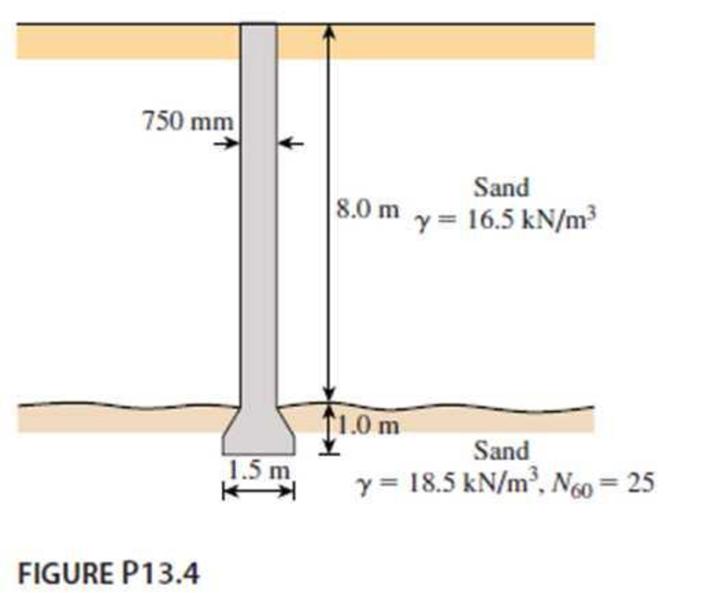
Chapter 13, Problem 13.4P
Determine the ultimate load-carrying capacity of the drilled shaft shown in Figure P13.4, using the Reese and O’Neill (1989) method.
Expert Solution & Answer

Trending nowThis is a popular solution!

Students have asked these similar questions
Define the Normalized Tip Resistance of Drilled Shafts in Sand (Ghionna et al. 1994) ?
For the drilled shaft described in Problem 10.1, what skin resistance would develop in the top 6 m, which are in clay ?
Earth Sciences
Downward force is 4000 kg and rotational force is 3000 kg. Contact surface area (cross sectional area) is 100 cm2. Also, the rock sample (diameter: 20 cm) is tested by a uniaxial compressive strength machine and the sample was cracked at 30000 kg. Answer the following questions:a. Find the resultant force acting on the rock formation.b. Find the bearing strength of the rock drilled.c. Can we drill under these circumstances?
Chapter 13 Solutions
Principles of Foundation Engineering (MindTap Course List)
Ch. 13 - Prob. 13.1PCh. 13 - Prob. 13.2PCh. 13 - Prob. 13.3PCh. 13 - Determine the ultimate load-carrying capacity of...Ch. 13 - For the same data given in Problem 13.4, determine...Ch. 13 - Prob. 13.6PCh. 13 - A 3 ft diameter straight drilled shaft is shown in...Ch. 13 - Prob. 13.8PCh. 13 - Figure P13.9 shows a drilled shaft extending into...Ch. 13 - A free-headed drilled shaft is shown in Figure...
Knowledge Booster


Learn more about
Need a deep-dive on the concept behind this application? Look no further. Learn more about this topic, civil-engineering and related others by exploring similar questions and additional content below.Similar questions
- For the same data given in Problem 13.4, determine the load-carrying capacity of the drilled shaft, limiting the settlement to 10.0 mm. 13.4 Determine the ultimate load-carrying capacity of the drilled shaft shown in Figure P13.4, using the Reese and ONeill (1989) method.arrow_forwardFor the drilled shaft described in Problem 19.7, determine these values: a. The ultimate load-carrying capacity b. The load-carrying capacity for a settlement of 25 mm Use the procedure outlined in Section 19.8. 19.7 Figure 19.16 shows a drilled shaft without a bell. Here, L1 = 6 m, L2 = 7 m, Ds = 1.5 m, cu(1) = 50 kN/m2, and cu(2) = 75 kN/m2. Find these values: a. The net ultimate point bearing capacity. Use Eqs. (19.23) and (19.24) b. The ultimate skin resistance. Use Eqs. (19.26) and (19.28) c. The working load, Qw (FS = 3) FIG. 19.16arrow_forwardA free-headed drilled shaft is shown in Figure P13.10. Let Qg = 260 kN, Mg = 0, = 17.5 kN/m3, = 35, c' = 0, and Ep = 22 106 kN/m2. Determine a. The ground line deflection, xo b. The maximum bending moment in the drilled shaft c. The maximum tensile stress in the shaft d. The minimum penetration of the shaft needed for this analysisarrow_forward
- A 3 ft diameter straight drilled shaft is shown in Figure P13.7. Determine the load-carrying capacity of the drilled shaft with FS = 3. Take / as 0.8 for the sand.arrow_forwardFigure P13.9 shows a drilled shaft extending into clay shale. Given: qu (clay shale) = 1.81 MN/m2. Considering the socket to be rough, estimate the allowable load-carrying capacity of the drilled shaft. Use FS = 4. Use the Zhang and Einstein procedure.arrow_forwardFor the drilled shaft described in Problem 19.7, estimate the total elastic settlement at working load. Use Eqs. (18.45), (18.47), and (18.48). Assume that Ep = 20 106 kN/m2, s = 0.3, Es = 12 103 kN/m2, = 0.65 and Cp = 0.03. Assume 80% mobilization of skin resistance at working load. (See Part c of Problem 19.7) 19.7 Figure 19.16 shows a drilled shaft without a bell. Here, L1 = 6 m, L2 = 7 m, Ds = 1.5 m, cu(1) = 50 kN/m2, and cu(2) = 75 kN/m2. Find these values: a. The net ultimate point bearing capacity. Use Eqs. (19.23) and (19.24) b. The ultimate skin resistance. Use Eqs. (19.26) and (19.28) c. The working load, Qw (FS = 3) FIG. 19.16arrow_forward
arrow_back_ios
arrow_forward_ios
Recommended textbooks for you
 Principles of Foundation Engineering (MindTap Cou...Civil EngineeringISBN:9781337705028Author:Braja M. Das, Nagaratnam SivakuganPublisher:Cengage Learning
 Principles of Foundation Engineering (MindTap Cou...Civil EngineeringISBN:9781305081550Author:Braja M. DasPublisher:Cengage Learning
 Fundamentals of Geotechnical Engineering (MindTap...Civil EngineeringISBN:9781305635180Author:Braja M. Das, Nagaratnam SivakuganPublisher:Cengage Learning
Principles of Foundation Engineering (MindTap Cou...
Civil Engineering
ISBN:9781337705028
Author:Braja M. Das, Nagaratnam Sivakugan
Publisher:Cengage Learning
Principles of Foundation Engineering (MindTap Cou...
Civil Engineering
ISBN:9781305081550
Author:Braja M. Das
Publisher:Cengage Learning
Fundamentals of Geotechnical Engineering (MindTap...
Civil Engineering
ISBN:9781305635180
Author:Braja M. Das, Nagaratnam Sivakugan
Publisher:Cengage Learning
Types of Foundation in building construction in detail - Civil Engineering Videos; Author: Civil Engineers;https://www.youtube.com/watch?v=7sl4KuM4UIE;License: Standard YouTube License, CC-BY
Types of Foundation || Foundation Engineering; Author: Civil Engineering;https://www.youtube.com/watch?v=AFLuAKGhanw;License: Standard Youtube License