
Fundamentals of Geotechnical Engineering (MindTap Course List)
5th Edition
ISBN: 9781305635180
Author: Braja M. Das, Nagaratnam Sivakugan
Publisher: Cengage Learning
expand_more
expand_more
format_list_bulleted
Concept explainers
Videos
Textbook Question
Chapter 19, Problem 19.8P
For the drilled shaft described in Problem 19.7, estimate the total elastic settlement at working load. Use Eqs. (18.45), (18.47), and (18.48). Assume that Ep = 20 × 106 kN/m2, μs = 0.3, Es = 12 × 103 kN/m2, ξ = 0.65 and Cp = 0.03. Assume 80% mobilization of skin resistance at working load. (See Part c of Problem 19.7)
19.7 Figure 19.16 shows a drilled shaft without a bell. Here, L1 = 6 m, L2 = 7 m, Ds = 1.5 m, cu(1) = 50 kN/m2, and cu(2) = 75 kN/m2. Find these values:
a. The net ultimate point bearing capacity. Use Eqs. (19.23) and (19.24)
b. The ultimate skin resistance. Use Eqs. (19.26) and (19.28)
c. The working load, Qw (FS = 3)
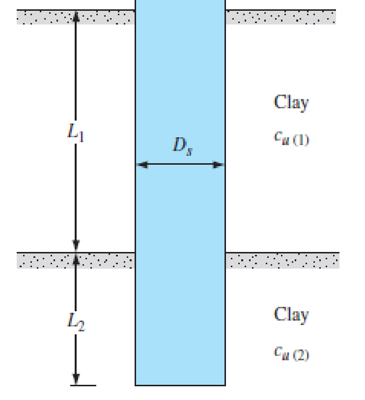
FIG. 19.16
Expert Solution & Answer
Want to see the full answer?
Check out a sample textbook solution
Students have asked these similar questions
Refer to Figure 11.26b. For the drilled shaft with bell, given:Thickness of active zone, Z = 9 mDead load = 1500 kN Live load = 300 kNDiameter of the shaft, Ds = 1 mZero swell pressure for the clay in the active zone = 600 kN/m2Average angle of plinth-soil friction, Φ'ps = 20°Average undrained cohesion of the clay around the bell = 150 kN/m2. Determine the diameter of the bell, Db. A factor of safety of 3 against uplift is required with the assumption that dead load plus live load is equal to zero.
For the drilled shaft described in Problem 10.1, what skin resistance would develop in the top 6 m, which are in clay ?
Define the Normalized Tip Resistance of Drilled Shafts in Sand (Ghionna et al. 1994) ?
Chapter 19 Solutions
Fundamentals of Geotechnical Engineering (MindTap Course List)
Ch. 19 - Prob. 19.1PCh. 19 - Prob. 19.2PCh. 19 - Redo Problem 19.2. Use Eq. (19.4) and Es = 600 pa....Ch. 19 - For the drilled shaft described in Problem 19.2,...Ch. 19 - Prob. 19.5PCh. 19 - Prob. 19.6PCh. 19 - Prob. 19.7PCh. 19 - For the drilled shaft described in Problem 19.7,...Ch. 19 - For the drilled shaft described in Problem 19.7,...Ch. 19 - Prob. 19.10P
Knowledge Booster


Learn more about
Need a deep-dive on the concept behind this application? Look no further. Learn more about this topic, civil-engineering and related others by exploring similar questions and additional content below.Similar questions
- A free-headed drilled shaft is shown in Figure P13.10. Let Qg = 260 kN, Mg = 0, = 17.5 kN/m3, = 35, c' = 0, and Ep = 22 106 kN/m2. Determine a. The ground line deflection, xo b. The maximum bending moment in the drilled shaft c. The maximum tensile stress in the shaft d. The minimum penetration of the shaft needed for this analysisarrow_forwardFor the drilled shaft described in Problem 19.7, determine these values: a. The ultimate load-carrying capacity b. The load-carrying capacity for a settlement of 25 mm Use the procedure outlined in Section 19.8. 19.7 Figure 19.16 shows a drilled shaft without a bell. Here, L1 = 6 m, L2 = 7 m, Ds = 1.5 m, cu(1) = 50 kN/m2, and cu(2) = 75 kN/m2. Find these values: a. The net ultimate point bearing capacity. Use Eqs. (19.23) and (19.24) b. The ultimate skin resistance. Use Eqs. (19.26) and (19.28) c. The working load, Qw (FS = 3) FIG. 19.16arrow_forwardAn embankment consists of clay fill for which c=25 kPa and angle of internal friction is 260 (from consolidated undrained test with pore pressure measurement) The weight of fill per unit volume is 18.64 kN/m3. Compute the effective stress in kPa at a depth of 20 m. If the pore pressure at this point is shown by a piezometer to be 180 kPa. a. 62.5 b. 372.8 c. 192.8 d. 21.6arrow_forward
- A mine has a 6m diameter vertical ventilation shaft. Calculate the radial, circumferential and shear stresses 0.2m into the rock at the north point (A) for a depth of 2500m below surface. Draw a simple sketch of the shaft showing the stresses, directions, the point A with proper labels. The principal in situ horizontal stress in the north-south direction is equal to half the overburden stress, and the principal in situ horizontal stress in the east- west direction is twice the overburden stress. The unit weight of the rock y is 0,025 MN/mº. The modulus of elasticity of the rock E is 50 GPa, and Poisson's ratio for the rock v is 0,25. Assume that the rock behaves elastically.arrow_forwardA 3 ft diameter straight drilled shaft is shown in Figure P13.7. Determine the load-carrying capacity of the drilled shaft with FS = 3. Take / as 0.8 for the sand.arrow_forward
arrow_back_ios
arrow_forward_ios
Recommended textbooks for you
 Fundamentals of Geotechnical Engineering (MindTap...Civil EngineeringISBN:9781305635180Author:Braja M. Das, Nagaratnam SivakuganPublisher:Cengage Learning
 Principles of Foundation Engineering (MindTap Cou...Civil EngineeringISBN:9781305081550Author:Braja M. DasPublisher:Cengage Learning
 Principles of Geotechnical Engineering (MindTap C...Civil EngineeringISBN:9781305970939Author:Braja M. Das, Khaled SobhanPublisher:Cengage Learning
 Principles of Foundation Engineering (MindTap Cou...Civil EngineeringISBN:9781337705028Author:Braja M. Das, Nagaratnam SivakuganPublisher:Cengage Learning
Fundamentals of Geotechnical Engineering (MindTap...
Civil Engineering
ISBN:9781305635180
Author:Braja M. Das, Nagaratnam Sivakugan
Publisher:Cengage Learning
Principles of Foundation Engineering (MindTap Cou...
Civil Engineering
ISBN:9781305081550
Author:Braja M. Das
Publisher:Cengage Learning
Principles of Geotechnical Engineering (MindTap C...
Civil Engineering
ISBN:9781305970939
Author:Braja M. Das, Khaled Sobhan
Publisher:Cengage Learning
Principles of Foundation Engineering (MindTap Cou...
Civil Engineering
ISBN:9781337705028
Author:Braja M. Das, Nagaratnam Sivakugan
Publisher:Cengage Learning
CE 414 Lecture 02: LRFD Load Combinations (2021.01.22); Author: Gregory Michaelson;https://www.youtube.com/watch?v=6npEyQ-2T5w;License: Standard Youtube License