
Concept explainers
Videos
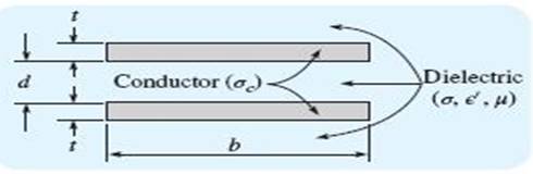
Pertinent dimensions for the transmission line shown in Figure 13.2 are b = 3 mm and d= 0.2 mm. The conductors and the dielectric are nonmagnetic. (a) If the characteristic impedance of the line is
(a)
The dielectric constant
Answer to Problem 13.7P
The dielectric constant
Explanation of Solution
Given:
The given figure is shown below..
 .
.
Calculation:
The characteristic impedance of the transmission line is given as:.
Conclusion:
Thus, the dielectric constant
(b)
The loss tangent of the dielectric, when
Answer to Problem 13.7P
The loss tangent of the dielectric, when
Explanation of Solution
Given:
The given figure is shown below:.
 .
.
Calculation:
For copper conductivity is
Thus, resistance can be calculated as:.
Capacitance can be calculated as:.
Inductance can be calculated as:.
As,
Conductivity can also be given as:.
The loss tangent is given as:.
Conclusion:
Thus, the loss tangent of the dielectric, when
Want to see more full solutions like this?
Chapter 13 Solutions
Engineering Electromagnetics


- The diameter of the overhead lines in the form of cylindrical conductors in a 300 kV three-phase transmission system is 20 mm. a) - How much distance should there be between two conductors using the maximum area calculation equations? Calculate. (Puncture peak strength of air is 30kV / cm.) b) - In this configuration, if the distance between phase conductors is 0 m, will discharge calculation? c) - Maximum electric field in the same configuration, for electrode distances to be A m Calculate the value. (When heard in calculations Ꜫ0 = 8.854x10⁻¹² F / m)arrow_forwardGeometric mean radius of a 400 kV, 200 km three-phase transmission line 20 mm dir. The roughness factor of the conductor is 0.8 and the geometric mean length between phases is 11 m. Air pressure along the line is 700 mm Hg and the temperature is 20 ° C. In this transmission line; a) - Calculate the corona voltage and the voltage at which ionization begins with impingement particles. b) - Find the total corona loss in the three phase system for the operating voltage with the Peek formula. c) - Find the total corona loss for 10% increase in operating voltage.arrow_forwardA 132 kV, three-phase, 50Hz transmission line uses 18 mm diameter, equally spaced conductors. Determine the spacing between these conductors, if it is to be designed such that the corona inception voltage is 5% higher than the normal operating voltage of the line at 40oC. (You may assume the expression relating the electric field and the voltage of the line as a starting point, m=0.9)arrow_forward
- A Three-Phase, 180 KV, 75 Hz Transmission Line consists of 1.2 cm radius conductors spaced at 2.4 meters apart in an equilateral triangular formation. If the Temperature is 40 ºC and Atmospheric Pressure is 76 cm of Hg, calculate the Corona Loss per km of the line. Take m0=0.8arrow_forwardA 300 km long 3-phase transmission line of 154 kV is operated at 60 Hz. The line is on average 1200 m above sea level and instead At 120m, an air outlet decreases by 10 mmHg. Sea free air the dose is 760 mmHg and the puncture strength of the air is 30 kV / cm As it is known, the roughness of the line is 0.89 for the average outdoor temperature of 34 oC, The distance between the conductors is 550 cm and the conductor cross section is 40mm. along the line by calculating the corona voltage and corona discharge voltage calculate the total corona loss that occurred.arrow_forward3. A single-phase, two-wire transmission line, 15 km long, is made up of round conductors, each0.8 cm in diameter, separated from each other by 40 cm. Calculate the equivalent diameter of afictitious hollow, thin-walled conductor having the same inductance as the original line. What isthe value of this inductance? Answer: 0.623 cm, 29.13 mHarrow_forward
- A Three-Phase, 50 Hz, 220 KV Transmission Line consists of conductors of 1.2 cm radius spaced 2 meters at the corners of an equilateral triangle. Calculate the Corona Power Loss per km of the line at a Temperature of 20ºC and Barometric Pressure of 72.2 cm of Hg. Take the Surface Factor of the conductor as 0.96arrow_forwardA 3-phase, 420 kV transmission line consists of 1·5 cm radius conductor spaced 2 meters apart in equilateral triangular formation. If the dielectric strength of air is 30 kV (max) per cm and corona loss per km of the line is 146.91kW/phase. Take air density factor ∂= 0·952 Estimate: i. irregularity factor ii. comment on type of conductorsarrow_forwardThe diameter of the overhead lines in the form of cylindrical conductors in a 380 kV three-phase transmission system is 28 mm.a) - How much distance should there be between two conductors using the maximum area calculation equations?Calculate. (Puncture peak strength of air is 30kV / cm.)b) - In this configuration, if the distance between phase conductors is 4m, at what voltage levelCalculate the discharge occurs?c) - Maximum electric field in the same configuration, for electrode distances to be 8mCalculate the value. If needed in calculations Ꜫ0 = 8.854x10⁻¹² F / m)arrow_forward
- A single-phase transmission line consisting of two conductors, the radius of each conductor is 0.4 cm, the distance between the conductors is three and half meters and the height above ground is eight meter. Determine 1)The capacitance in uF/km without effect of ground 2)The capacitance in uF/km with effect of groundarrow_forward.A 3-phase, 220 k 50Hz transmission line consists of 1.5 cm radius conductor spaced 2 metres apart in equilateral triangular formation. If the temperature is 40°C and atmospheric pressure is 76 cm, calculate the corona loss per km of the line. Take m = 0.85arrow_forwardHIGH VOLTAGE . A 132 kV, three-phase, 50Hz transmission line uses 18 mm diameter, equally spaced ACSR conductors. Determine the spacing between these conductors, if it is to be designed such that the corona inception voltage is 5% higher than the normal operating voltage of the line at 40o You may assume the expression relating the electric field and the voltage of the line as a starting point.arrow_forward
 Power System Analysis and Design (MindTap Course ...Electrical EngineeringISBN:9781305632134Author:J. Duncan Glover, Thomas Overbye, Mulukutla S. SarmaPublisher:Cengage Learning