
PROGRAMMABLE LOGIC CONTROLLERS BUNDLE
5th Edition
ISBN: 9781260582475
Author: Petruzella
Publisher: MCG
expand_more
expand_more
format_list_bulleted
Concept explainers
Videos
Textbook Question
Chapter 13, Problem 14P
The
- a. Examine the ladder logic and describe how the circuit would operate as programmed.
- b. Troubleshoot the program and identify what needs to be changed to have it operate properly.
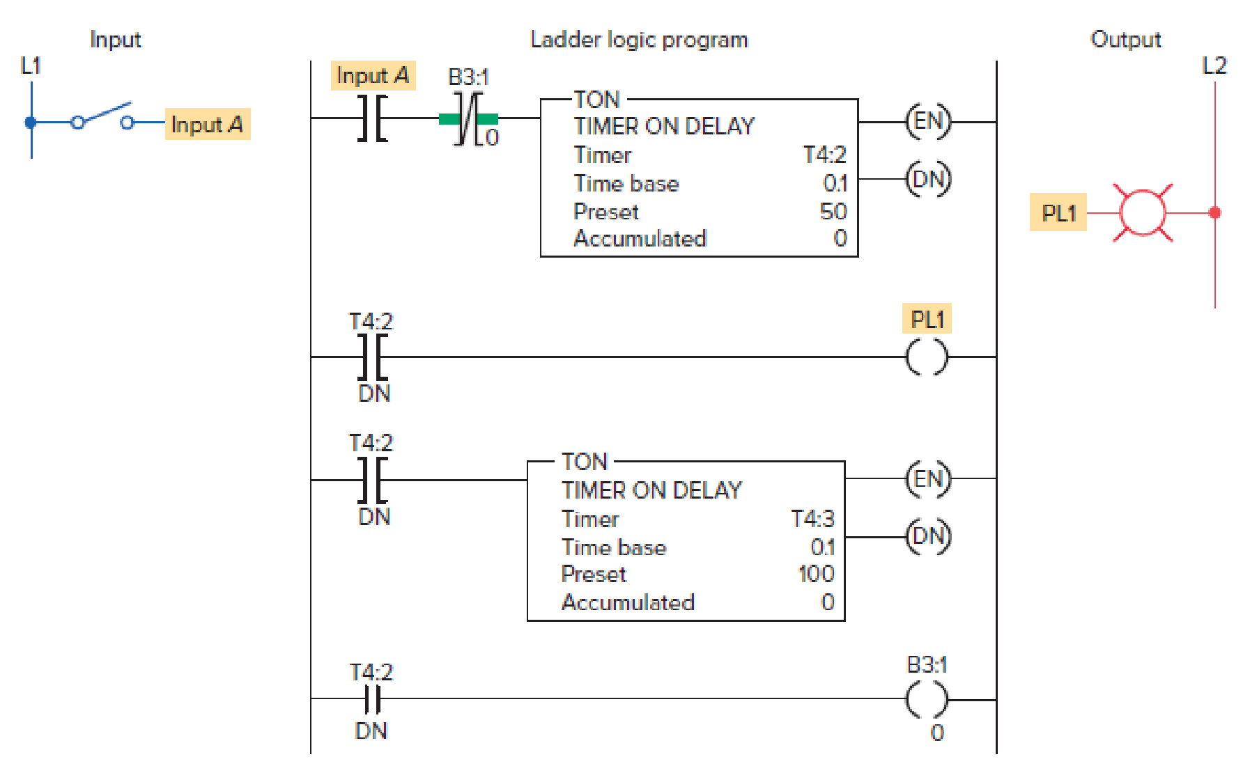
Figure 13-39 Program for Problem 14.
Expert Solution & Answer
Want to see the full answer?
Check out a sample textbook solution
Students have asked these similar questions
Use the following state diagram and create the state table for a synchronous to detect the sequence. The circuit has a single input, x, and a single output z. The output is logic-1 whenever the input sequence 101 is detected, logic-0 otherwise. Note that overlapping sequences are allowed, Create the initial state table, and the complete state table. Write the equations for all the state variables and the output z.
Designs a logic circuit that will allow a signal to pass to the output only when control inputs B and C are both HIGH; otherwise, the output will stay LOW
Design a logic circuit with input signal A, control input B, and outputs X and Y to operate as follows:
When B = 1, output X will follow input A, and output Y will be 0.
When B = 0, output X will be 0, and output Y will follow input A.
Chapter 13 Solutions
PROGRAMMABLE LOGIC CONTROLLERS BUNDLE
Ch. 13 - Prob. 1RQCh. 13 - Prob. 2RQCh. 13 - Prob. 3RQCh. 13 - List three potential noise-generating inductive...Ch. 13 - Prob. 5RQCh. 13 - Prob. 6RQCh. 13 - Prob. 7RQCh. 13 - Under what condition can a ground loop circuit be...Ch. 13 - Prob. 9RQCh. 13 - What operating state will cause an inductive load...
Ch. 13 - Prob. 11RQCh. 13 - Prob. 12RQCh. 13 - Prob. 13RQCh. 13 - Prob. 14RQCh. 13 - Prob. 15RQCh. 13 - List four uses for the data monitor function.Ch. 13 - Prob. 17RQCh. 13 - Prob. 18RQCh. 13 - Prob. 19RQCh. 13 - Prob. 20RQCh. 13 - Prob. 21RQCh. 13 - Prob. 22RQCh. 13 - Prob. 23RQCh. 13 - Prob. 24RQCh. 13 - Prob. 25RQCh. 13 - Prob. 26RQCh. 13 - Prob. 27RQCh. 13 - Prob. 28RQCh. 13 - Prob. 29RQCh. 13 - Prob. 30RQCh. 13 - Prob. 1PCh. 13 - A fuse is blown in an output module. Suggest two...Ch. 13 - Prob. 3PCh. 13 - Prob. 4PCh. 13 - Prob. 5PCh. 13 - Prob. 6PCh. 13 - A specific output is forced on, but the LED module...Ch. 13 - An electronic-based input sensor is wired to a...Ch. 13 - Prob. 9PCh. 13 - Prob. 11PCh. 13 - Prob. 12PCh. 13 - Prob. 13PCh. 13 - The program of Figure 13-39 is supposed to execute...
Knowledge Booster


Learn more about
Need a deep-dive on the concept behind this application? Look no further. Learn more about this topic, computer-science and related others by exploring similar questions and additional content below.Similar questions
- FIGURE 11.55 is a state transition diagram for a sequential circuit with three flip-flops and one input. It counts up in binary when the input is 1 and counts down when the input is 0. Design the circuit and draw the logic diagram using the following flip-flops: (b) SRarrow_forwardWrite the three outputs of X, Y and Z in terms of the four inputs A, B, C and D for the follow logic gates configuration ---This is my answer: I am unsure if it is right. X = A + (A’B’ * (B’+C’) = A + (A’+B’)*(B’*C’) Y = ((A’+B’)*(B’*C’))*((B’*C’)+CD)Z = (B+C)*(C’+D’)*D’arrow_forwarda) Write the Boolean expression for output x in the circuit. b) Create a complete analysis table for the circuit by finding the logic levels present at each gate output for each of the 16 possible input combinations. Hint: You can use nodes/intermediate columns in truth table after each logical gate operation to facilitate the work. Which is the answer? I need all the steps to understand, thanks.arrow_forward
- Analyse the sequential circuit shown in Figure which has 2 rising edge-triggered flip-flops A and B, one input X, and one output Z. You are required to perform the following tasks: Write the state equations, flip-flop equations and output equation for this circuit. Construct a state table. Draw a state diagram of this circuitarrow_forwardDesign a combinational circuit with four inputs— A, B, C, and D —and one output, F . F is to be equal to 1when A = 1, provided that B = 0, or when B = 1, provided that either C or D is also equal to 1. Otherwise,the output is to be equal to 0.1. Obtain the truth table of the circuit.2. Simplify the output function.3. Draw the logic diagram of the circuit, using NAND gates with a minimum number of ICs.4. Construct the circuit and test it for proper operation by verifying the given conditions.arrow_forwardDesign 4-input ( D,A,W,O) one output (y) conbinational logic circuit for the following input- output condition 1-if number of 1’s input is less than 3 then the output is 1 2- -if number of 1’s input is more than or equal to 3 then the output is 0arrow_forward
- What operation is performed in the up-down counter of Fig. 6.13 when both the up and down inputs are enabled? Modify the circuit so that when both inputs are equal to 1, the counter does not change state.arrow_forwarda) Build your circuit Design and build a state machine that will control the transition between light settings of a traffic light unit as shown in Figure 1. The design should include 3 positive edge triggered D flip-flops. Use 1 flip-flop to control the on and off of a given light, and the state machine should switch from Red (100) -> Red and Amber (110) - > Green (001) -> Amber (010) and repeat the cycle again, with the transition table below.arrow_forwardWrite the three outputs of X, Y and Z in terms of the four inputs A, B, C and D for the follow logic gates configurationarrow_forward
- subject: Digital Logic &Design Q: Determine the A = B, A > B, and A < B outputs for the input numbers shown on thecomparator in Figure 02.arrow_forwardA clock pulse of 10 seconds period is used to clock a 3bit binary counter that counts from 0 to 7. The outputs of the three bistables are used as inputs to a combinational circuit that controls the sequence of the traffic lights , green, amber, red, amber&red. Green light is ON for 30 seconds. Amber is ON for 10 sec. Red is ON for 30 sec. Amber & Red light is ON for 10 sec and so on. (ON = Logic 1) Design the circuit by using D Flip flop and 12H6 PAL. Thank you.arrow_forward(a) Write the logic expression for the output'Y' of the circuit given below. (b) Write the Truth table and pin diagram for EXOR gatearrow_forward
arrow_back_ios
SEE MORE QUESTIONS
arrow_forward_ios
Recommended textbooks for you
 Database System ConceptsComputer ScienceISBN:9780078022159Author:Abraham Silberschatz Professor, Henry F. Korth, S. SudarshanPublisher:McGraw-Hill Education
 Starting Out with Python (4th Edition)Computer ScienceISBN:9780134444321Author:Tony GaddisPublisher:PEARSON
 Digital Fundamentals (11th Edition)Computer ScienceISBN:9780132737968Author:Thomas L. FloydPublisher:PEARSON
 C How to Program (8th Edition)Computer ScienceISBN:9780133976892Author:Paul J. Deitel, Harvey DeitelPublisher:PEARSON
 Database Systems: Design, Implementation, & Manag...Computer ScienceISBN:9781337627900Author:Carlos Coronel, Steven MorrisPublisher:Cengage Learning
 Programmable Logic ControllersComputer ScienceISBN:9780073373843Author:Frank D. PetruzellaPublisher:McGraw-Hill Education
Database System Concepts
Computer Science
ISBN:9780078022159
Author:Abraham Silberschatz Professor, Henry F. Korth, S. Sudarshan
Publisher:McGraw-Hill Education
Starting Out with Python (4th Edition)
Computer Science
ISBN:9780134444321
Author:Tony Gaddis
Publisher:PEARSON
Digital Fundamentals (11th Edition)
Computer Science
ISBN:9780132737968
Author:Thomas L. Floyd
Publisher:PEARSON
C How to Program (8th Edition)
Computer Science
ISBN:9780133976892
Author:Paul J. Deitel, Harvey Deitel
Publisher:PEARSON
Database Systems: Design, Implementation, & Manag...
Computer Science
ISBN:9781337627900
Author:Carlos Coronel, Steven Morris
Publisher:Cengage Learning
Programmable Logic Controllers
Computer Science
ISBN:9780073373843
Author:Frank D. Petruzella
Publisher:McGraw-Hill Education
Tutorial: Photoconductivity; Author: MIT OpenCourseWare;https://www.youtube.com/watch?v=20GlFVyxqHY;License: Standard YouTube License, CC-BY
photoconductive cell; Author: Electronics Engineering;https://www.youtube.com/watch?v=Bxo3v_5QGaA;License: Standard Youtube License