
Electronics Fundamentals: Circuits, Devices & Applications
8th Edition
ISBN: 9780135072950
Author: Thomas L. Floyd, David Buchla
Publisher: Prentice Hall
expand_more
expand_more
format_list_bulleted
Videos
Textbook Question
Chapter 13, Problem 16P
Find the total impedance of the circuit in Figure 13-72.
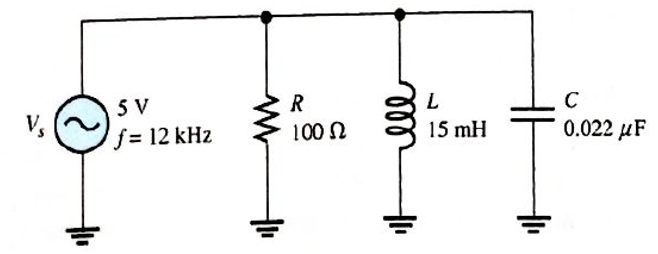
Figure 13-72
Expert Solution & Answer
Want to see the full answer?
Check out a sample textbook solution
Students have asked these similar questions
Determine the total inductance of each circuit in Figure 13-50
Compute the impedance of a series RL circuit with the following values:
R = 114 ΩL = 347 mHf = 60 hz
Take R=89
Chapter 13 Solutions
Electronics Fundamentals: Circuits, Devices & Applications
Ch. 13 - A series RLC circuit can have a higher voltage...Ch. 13 - The impedance of a series RLC circuit is dependent...Ch. 13 - Above the resonant frequency, series resonant...Ch. 13 - Prob. 4TFQCh. 13 - Prob. 5TFQCh. 13 - The upper and lower cutoff frequencies of a...Ch. 13 - Prob. 7TFQCh. 13 - The Q of a band-pass filter does not affect the...Ch. 13 - Prob. 9TFQCh. 13 - Prob. 10TFQ
Ch. 13 - Prob. 1STCh. 13 - The phase angle of a series RLC circuit at...Ch. 13 - The impedance at the resonant frequency of a...Ch. 13 - In a series RLC circuit that is operating below...Ch. 13 - Prob. 5STCh. 13 - Prob. 6STCh. 13 - Prob. 7STCh. 13 - Prob. 8STCh. 13 - Prob. 9STCh. 13 - Prob. 10STCh. 13 - Prob. 11STCh. 13 - Prob. 12STCh. 13 - A certain series RLC circuit operates at a...Ch. 13 - Find the impedance in Figure 13-66.Ch. 13 - If the frequency of the source voltage in Figure...Ch. 13 - For the circuit in figure 13-66, find Itot,VR,VL,...Ch. 13 - Draw the voltage phasor diagram for the circuit in...Ch. 13 - Analyze the circuit in Figure 13-67 for the...Ch. 13 - For the circuit in Figure 13-66, is the resonant...Ch. 13 - For the circuit in Figure 13-68, determine the...Ch. 13 - Find XL,XC,Z, and I at the resonant frequency in...Ch. 13 - A certain series resonant circuit has a maximum...Ch. 13 - For the RLC circuit in Figure 13-69, determine the...Ch. 13 - What is the value of the current at the half-power...Ch. 13 - Determine the resonant frequency for each filter...Ch. 13 - FIGURE 13-70 Assuming that the coils in Figure...Ch. 13 - Determine fr and BW for each filter in Figure...Ch. 13 - Find the total impedance of the circuit in Figure...Ch. 13 - Is the circuit in Figure 13-72 capacitive or...Ch. 13 - For the circuit in Figure 13-72, find all the...Ch. 13 - Find the total impedence for the circuit in Figure...Ch. 13 - What is the impedance of an ideal parallel...Ch. 13 - Prob. 21PCh. 13 - How much current is drawn from the source in...Ch. 13 - At resonance, XL=2K and RW=25 in a parallel...Ch. 13 - If the lower cutoff frequency is 2400 Hz and the...Ch. 13 - In a certain resonant circuit, the power to the...Ch. 13 - What values of L and C should be used in a tank...Ch. 13 - Prob. 27PCh. 13 - A parallel resonant band-stop filter is needed to...Ch. 13 - Prob. 29PCh. 13 - Prob. 30PCh. 13 - Prob. 31PCh. 13 - Determine whether there is a value of C that will...Ch. 13 - If the value of C is 0.22F, how much current is...Ch. 13 - Determine the resonant frequencies in Figure 13-77...Ch. 13 - Prob. 35PCh. 13 - Prob. 36PCh. 13 - Prob. 37PCh. 13 - Prob. 39PCh. 13 - Prob. 40PCh. 13 - Prob. 41PCh. 13 - Open file P13-42. Determine if there is a fault...Ch. 13 - Prob. 43P
Knowledge Booster


Learn more about
Need a deep-dive on the concept behind this application? Look no further. Learn more about this topic, electrical-engineering and related others by exploring similar questions and additional content below.Similar questions
- Assume the circuit shown in Figure 21-1 has an apparent power of 432 VA and a true power of 345.6 W. The capacitor has a capacitance of 15.8919 F, and the frequency is 60 Hz. Find the missing values. ET ER EC IT IR IC Z R XC VA432 P345.6W VARSC PF C15.8919Farrow_forwardAssume the circuit shown in Figure 17-2 has a power factor of 78%, an apparent power of 374.817 VA, and a frequency of 400 Hz. The inductor has an inductance of 0.0382 H. ETITZVA374.817PF78%ERIRRPELILXLVARsLL0.0382Harrow_forwardConsider the sinusoidal voltage and current for an inductor. If you are given the phase angle of the voltage, the phase angle of the current will be:a) The same as the voltage phase angleb) 90°more than the voltage phase anglec) 90° less than the voltage phase angled) Dependent on the inductancearrow_forward
- An RC series circuit is connected to a 277 volt 60Hz line. the apparent power of the ciruit is 8.2 kVA. what is the impedance of the ciruit?arrow_forwardThe hypotenuse side of the power triangle is equal to Reactive power Active power Apparent power True powerarrow_forward11 - In the series R-L circuit, AA 12 V with a frequency of 50 Hz is applied to the ends of the coil with a resistance of 10 Ω and an inductance of 20 mH.Which of the following is the phase difference (power factor) between the current passing through the circuit and the voltage?A) 0.42B) 0.21C) 0.5D) 0.84E) 0.45arrow_forward
- A. Calculate the value of the lower cutoff frequency. Express your answer in radians per second to three significant figures. B. Calculate the value of the upper cutoff frequency. Express your answer in radians per second to three significant figures.arrow_forward3. A coil has an impedance of 75.4 when connected a across a source of 60 Hz. The same coil yields an impedance of 54.8 when connected across a source having a different frequency of 30 Hz. What is the coil's inductance?arrow_forwardWhat is the phase angle between source voltage and current in a series circuit consisting of an alternating current source of frequency 60 Hz, a resistor of 100 Ω, and an inductor of 250 mH?arrow_forward
arrow_back_ios
SEE MORE QUESTIONS
arrow_forward_ios
Recommended textbooks for you
 Delmar's Standard Textbook Of ElectricityElectrical EngineeringISBN:9781337900348Author:Stephen L. HermanPublisher:Cengage Learning
Delmar's Standard Textbook Of Electricity
Electrical Engineering
ISBN:9781337900348
Author:Stephen L. Herman
Publisher:Cengage Learning
02 - Sinusoidal AC Voltage Sources in Circuits, Part 1; Author: Math and Science;https://www.youtube.com/watch?v=8zMiIHVMfaw;License: Standard Youtube License