
SHIGLEY'S MECH.ENGIN....(LOOSE)>CUSTOM<
10th Edition
ISBN: 9781260163155
Author: BUDYNAS
Publisher: MCG CUSTOM
expand_more
expand_more
format_list_bulleted
Concept explainers
Videos
Textbook Question
thumb_up100%
Chapter 13, Problem 16P
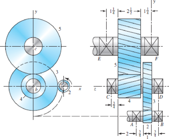
The double-reduction helical gearset shown in the figure is driven through shaft a at a speed of 700 rev/min. Gears 2 and 3 have a normal diametral pitch of 12 teeth/in, a 30° helix angle, and a normal pressure angle of 20°. The second pair of gears in the train, gears 4 and 5, have a normal diametral pitch of 8 teeth/in, a 25° helix angle, and a normal pressure angle of 20°. The tooth numbers are: N2 = 12, N3 = 48, N4 = 16, N5 = 36. Find:
(a) The directions of the thrust force exerted by each gear upon its shaft
(b) The speed and direction of shaft c
(c) The center distance between shafts
Problem 13–16
Dimensions in inches.
Expert Solution & Answer
Want to see the full answer?
Check out a sample textbook solution
Students have asked these similar questions
A gear train is composed of four helical gears with the three shaft axes in a single plane, as shown in the figure. The gears have a normal pressure angle of 20 and a 30 helix angle. Gear
is the driver, and is rotating counterclockwise as viewed from the top. Shaft b is an idler and the transmitted load from gear 2 to gear 3 is 500 Ibf. The gears on shaft b both have a normal diametral pitch of 7 teeth/in and have 54 and 14 teeth, respectively. Find the forces exerted by
gears 3 and 4 on shaft b
An epicyclic gear shown in figure below consists of ring gear, planet gear and sun gear. The ring gear has 72 internal teeth and sun gear has 32 external teeth. Planet gear meshes with both ring and sun gears and is carried on an arm which rotates about the centre of the ring gear at 20 r.p.m. If the gear A is fixed,
Calculate the speed of plane gear.
A gear train is composed of four helical gears with the tree shaft axes in a single plane, as shown in the figure. The gears have a normal pressure angle of 20° and a 30°helix angle. Gear 2 is the driver, and is rotating counterclockwise as viewed from the top. Shaft b is and idler and the transmitted load from gear 2 to gear 3 is 500 lbf. The gears on shaft b both have a normal diametral pitch of 7 teeth/in and have 54 and 14 teeth, respectively. Find the forces exerted by gears 3 and 4 on shaft b.
Chapter 13 Solutions
SHIGLEY'S MECH.ENGIN....(LOOSE)>CUSTOM<
Ch. 13 - A 17-tooth spur pinion has a diametral pitch of 8...Ch. 13 - A 15-tooth spur pinion has a module of 3 mm and...Ch. 13 - A spur gearset has a module of 6 mm and a velocity...Ch. 13 - A 21-tooth spur pinion mates with a 28-tooth gear....Ch. 13 - A 20 straight-tooth bevel pinion having 14 teeth...Ch. 13 - A parallel helical gearset uses a 20-tooth pinion...Ch. 13 - A parallel helical gearset consists of a 19-tooth...Ch. 13 - To avoid the problem of interference in a pair of...Ch. 13 - Prob. 9PCh. 13 - Prob. 10P
Ch. 13 - Prob. 11PCh. 13 - Prob. 12PCh. 13 - Prob. 13PCh. 13 - Prob. 14PCh. 13 - A parallel-shaft gearset consists of an 18-tooth...Ch. 13 - The double-reduction helical gearset shown in the...Ch. 13 - Shaft a in the figure rotates at 600 rev/min in...Ch. 13 - The mechanism train shown consists of an...Ch. 13 - The figure shows a gear train consisting of a pair...Ch. 13 - A compound reverted gear trains are to be designed...Ch. 13 - Prob. 21PCh. 13 - Prob. 22PCh. 13 - Prob. 23PCh. 13 - A gearbox is to be designed with a compound...Ch. 13 - The tooth numbers for the automotive differential...Ch. 13 - Prob. 26PCh. 13 - In the reverted planetary train illustrated, find...Ch. 13 - Prob. 28PCh. 13 - Tooth numbers for the gear train shown in the...Ch. 13 - The tooth numbers for the gear train illustrated...Ch. 13 - Shaft a in the figure has a power input of 75 kW...Ch. 13 - The 24T 6-pitch 20 pinion 2 shown in the figure...Ch. 13 - The gears shown in the figure have a module of 12...Ch. 13 - The figure shows a pair of shaft-mounted spur...Ch. 13 - Prob. 35PCh. 13 - Prob. 36PCh. 13 - A speed-reducer gearbox containing a compound...Ch. 13 - For the countershaft in Prob. 3-72, p. 152, assume...Ch. 13 - Prob. 39PCh. 13 - Prob. 40PCh. 13 - Prob. 41PCh. 13 - Prob. 42PCh. 13 - The figure shows a 16T 20 straight bevel pinion...Ch. 13 - The figure shows a 10 diametral pitch 18-tooth 20...Ch. 13 - Prob. 45PCh. 13 - The gears shown in the figure have a normal...Ch. 13 - Prob. 47PCh. 13 - Prob. 48PCh. 13 - Prob. 49PCh. 13 - The figure shows a double-reduction helical...Ch. 13 - A right-hand single-tooth hardened-steel (hardness...Ch. 13 - The hub diameter and projection for the gear of...Ch. 13 - A 2-tooth left-hand worm transmits 34 hp at 600...
Knowledge Booster


Learn more about
Need a deep-dive on the concept behind this application? Look no further. Learn more about this topic, mechanical-engineering and related others by exploring similar questions and additional content below.Similar questions
- Shaft a in the figure has a power input of 75 kW at a speed of 1000 rev/min in the counterclockwise direction. The gears have a module of 5 mm and a 20° pressure angle. Gear 3 is an idler (b) Find the torque T4c that gear 4 exerts on shaft c.arrow_forwardTwo parallel shafts have an angular velocity ratio of 4 to 1 are connected by gears, the largest of which has 40 teeth. Find the number of teeth of smaller gear.arrow_forward13–31 Shaft a in the figure has a power input of 75 kW at a speed of 1000 rev/min in the counterclockwise direction. The gears have a module of 5 mm and a 20° pressure angle. Gear 3 is an idler.(a) Find the force F3b that gear 3 exerts against shaft b.arrow_forward
- The top half of a compound Epicyclic gearset is shown in Figure, with input shaft I rotating at a constant speed of 700 rpm in a clockwise direction and generating 12 kW input power. The Annulus wheel A2 isform a compound wheel with gear O and connected to an auxiliary gear N on shaft X. . The Annulus A1 rotates in a counter-clockwise direction at a speed of 5,300 rpm. Calculate the following using this condition: The speed and direction of output shaft O (NO), shaft X (NX) and gear ratio (n). If Annulus wheel A1 is locked calculate the speed and direction of output shaft O (NO), shaft X (NX) and gear ratio (n). The braking torque (Tb) (magnitude and direction) that must be applied to Annulus wheel A1 to hold it stationary, assuming gear transmission efficiency is 90%. Number of gear teeth:P1 = 30 , A1 = 120P2 = 50 , A2 = 140N = 60 , O = 120arrow_forwardThe figure shows a double-reduction helical gearset. Pinion 2 is the driver, and it receives a torque of 1200 Ibf • in from its shaft in the direction shown. Pinion 2 has a normal diametral pitch of 8 teeth/in, 14 teeth, and a normal pressure angle of 20° and is cut right-handed with a helix angle of 30°. The mating gear 3 on shaft b has 36 teeth. Gear 4, which is the driver for the second pair of gears in the train, has a normal diametral pitch of 3 teeth/in, 15 teeth, and a normal pressure angle of 20° and is cut left-handed with a helix angle of 15°. Mating gear S has 45 teeth. Find the magnitude and direction of the force exerted by the bearings C and D on shaft b if bearing C can take only a radial load while bearing D is mounted to take both radial and thrust loads.arrow_forwardA pair of helical gears transmit 15 KW power and the pinion is rotating at 1000 rpm. The helix angle is 0.50 radians and the normal pressure angle is 0.35 radians. The pitch diameter of the pinion is 70 mm and the pitch diameter of the gear is 210 mm. Determine the tangential, radial, and axial forces between the gear teeth.arrow_forward
- The upper half of a compound Epicyclic gearset is shown in Figure, with input shaft I rotating at a constant speed of 700 rpm in a clockwise direction and generating 12 kW input power. The Annulus wheel A2 is coupled to an auxiliary gear N on shaft X and forms a compound wheel with gear O. The Annulus A1 rotates in a counter-clockwise direction at a speed of 5,300 rpm. Calculate the following using this condition: Number of gear teeth:P1 = 30 , A1 = 120P2 = 50 , A2 = 140N = 60 , O = 120 a) The output shaft O (NO), shaft X (NX), and gear ratio speed and direction (n). b) Calculate the speed and direction of output shaft O (NO), shaft X (NX), and gear ratio if Annulus wheel A1 is locked (n). c) The braking torque (Tb) that must be applied to Annulus wheel A1 to keep it stationary (magnitude and direction), assuming gear transmission efficiency of 90%.arrow_forward(Q.1) A compound epicyclic gear is shown in Fig. for Q.1. The shaft P is drivenat 3000 rev/min while the annulus A2 is driven at 1000 rev/min in theopposite direction. The numbers of teeth in the gears are S1, 16; S2,24; A1, 60; A2, 90. Determine the speed and direction of rotation ofshaft Q. (Q.2) A compound epicyclic gear is shown in Fig. for Q.2. C and D form acompound wheel which rotates freely on shaft G. The planet wheels B andE rotate on pins fixed in arms attached to shaft G. C and F have internalteeth: the others have external teeth with the following numbers: A, 40;B, 30; D, 50; E, 20. If A rotates at 500 rev/min and wheel F is fixed,find the speed of shaft G.arrow_forwardIn the pulley system shown in the figure, while the P gear rotates in the direction of 1 with its angular velocity, find the direction and angular velocity values of the other gears. Hint: The speed of the gears is equal at the point of contact. The speed of a belt is the same at all points.( w=3 rad/s , rk=0.8m ,rL=0.2 m ,rM=0.2m, rN=0.5m rP=0.4m rR=0.4marrow_forward
- A Coniflex, straight-tooth bevel gearset is supported on shafts with centerlines intersecting at a 90° angle. The gear is straddle mounted between closely positioned bearings, and the pinion overhangs its support bearing. The 15-tooth pinion rotates at 900 rpm, driving the 60-tooth gear, which has a di- ametral pitch of 6, pressure angle of 20°, and face width of 1.25 inches. The material for both gears is through-hardened Grade I steel with a hardness of BHN 300 (see Figure). It is desired to have a reliability of 90 percent, a design life of 10° cy- cles, and a governing safety factor of 2.5. Estimate the maximum horsepower that can be transmitted by this gear re- ducer while meeting all of the design specifications given.arrow_forwardThe intermediate shaft of a two-stage gearbox is given in the figure. P = 4 kW power is transmitted at n = 150 rpm with the help of two helical gears on the shaft.The forces acting on the gears are given as Ft1 = 5092 N, Fr1 = 1972 N, Fa1 = 1853 N, Ft2 = 2546 N, Fr2 = 986 N, Fa2 = 926 N. Diameter of small helical gear d1 = 100 mm, largethe diameter of the gear is d2 = 200 mm. Shaft material yield strength 335 MPa, tensile strength 600 MPa, Kç = 1.95, ka = 0.895, kb = 0.90 and safety coefficient = 1.4now thatarrow_forwarda in the figure has a power input of 75 kW at a speed of 1000 rev/min in the counterclock- wise direction. The gears have a module of 5 mm and a 20° pressure angle. Gear 3 is an idler. (a) Find the force F3b that gear 3 exerts against shaft b. (b) Find the torque T4c that gear 4 exerts on shaftarrow_forward
arrow_back_ios
SEE MORE QUESTIONS
arrow_forward_ios
Recommended textbooks for you
 Elements Of ElectromagneticsMechanical EngineeringISBN:9780190698614Author:Sadiku, Matthew N. O.Publisher:Oxford University Press
 Mechanics of Materials (10th Edition)Mechanical EngineeringISBN:9780134319650Author:Russell C. HibbelerPublisher:PEARSON
 Thermodynamics: An Engineering ApproachMechanical EngineeringISBN:9781259822674Author:Yunus A. Cengel Dr., Michael A. BolesPublisher:McGraw-Hill Education
 Control Systems EngineeringMechanical EngineeringISBN:9781118170519Author:Norman S. NisePublisher:WILEY
 Mechanics of Materials (MindTap Course List)Mechanical EngineeringISBN:9781337093347Author:Barry J. Goodno, James M. GerePublisher:Cengage Learning
 Engineering Mechanics: StaticsMechanical EngineeringISBN:9781118807330Author:James L. Meriam, L. G. Kraige, J. N. BoltonPublisher:WILEY
Elements Of Electromagnetics
Mechanical Engineering
ISBN:9780190698614
Author:Sadiku, Matthew N. O.
Publisher:Oxford University Press
Mechanics of Materials (10th Edition)
Mechanical Engineering
ISBN:9780134319650
Author:Russell C. Hibbeler
Publisher:PEARSON
Thermodynamics: An Engineering Approach
Mechanical Engineering
ISBN:9781259822674
Author:Yunus A. Cengel Dr., Michael A. Boles
Publisher:McGraw-Hill Education
Control Systems Engineering
Mechanical Engineering
ISBN:9781118170519
Author:Norman S. Nise
Publisher:WILEY
Mechanics of Materials (MindTap Course List)
Mechanical Engineering
ISBN:9781337093347
Author:Barry J. Goodno, James M. Gere
Publisher:Cengage Learning
Engineering Mechanics: Statics
Mechanical Engineering
ISBN:9781118807330
Author:James L. Meriam, L. G. Kraige, J. N. Bolton
Publisher:WILEY
Power Transmission; Author: Terry Brown Mechanical Engineering;https://www.youtube.com/watch?v=YVm4LNVp1vA;License: Standard Youtube License