
SHIGLEY'S MECHANICAL ENGR DESIGN (LL)
10th Edition
ISBN: 9781308945446
Author: BUDYNAS
Publisher: MCG/CREATE
expand_more
expand_more
format_list_bulleted
Concept explainers
Videos
Textbook Question
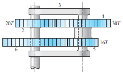
Chapter 13, Problem 27P
In the reverted planetary train illustrated, find the speed and direction of rotation of the arm if gear 2 is unable to rotate and gear 6 is driven at 12 rev/min in the clockwise direction as viewed from the bottom of the figure.
Problem 13-27
Expert Solution & Answer
Want to see the full answer?
Check out a sample textbook solution
Students have asked these similar questions
Find the output speed and cycle rate, since the input speed in the gear mechanism in the figure is
900 rpm, r2=20cm, r3=8cm, r4=12cm, r5=26cm, r6=32cm, r7=6cm
`input
2
out
4
5
4. For the gear train in a watch shown in the following
figure. The teeth number are z,=20,
z,=40, Z3=18, z4-50,
Z5=25, Z6-20, z,=54. Please calculate Speed ratio
17
1
VIIA
3
5
4
6
2
7
As shown in the figure a planetary gear train consist of the arm C coupled to two gears A
and B with 40 and 60 teeth respectively. If the arm rotates at 150 rpm in the anticlockwise
direction about the center of the fixed gear A. Calculate the speed of gear B. How fast will
gear B move if the gear A makes 300 rpm in the clockwise direction instead of being fixed.
(must use Tabular method)
B
Arm C
C
A
B
Nber of teeth
Total rotations
Chapter 13 Solutions
SHIGLEY'S MECHANICAL ENGR DESIGN (LL)
Ch. 13 - A 17-tooth spur pinion has a diametral pitch of 8...Ch. 13 - A 15-tooth spur pinion has a module of 3 mm and...Ch. 13 - A spur gearset has a module of 6 mm and a velocity...Ch. 13 - A 21-tooth spur pinion mates with a 28-tooth gear....Ch. 13 - A 20 straight-tooth bevel pinion having 14 teeth...Ch. 13 - A parallel helical gearset uses a 20-tooth pinion...Ch. 13 - A parallel helical gearset consists of a 19-tooth...Ch. 13 - To avoid the problem of interference in a pair of...Ch. 13 - Prob. 9PCh. 13 - Prob. 10P
Ch. 13 - Prob. 11PCh. 13 - Prob. 12PCh. 13 - Prob. 13PCh. 13 - Prob. 14PCh. 13 - A parallel-shaft gearset consists of an 18-tooth...Ch. 13 - The double-reduction helical gearset shown in the...Ch. 13 - Shaft a in the figure rotates at 600 rev/min in...Ch. 13 - The mechanism train shown consists of an...Ch. 13 - The figure shows a gear train consisting of a pair...Ch. 13 - A compound reverted gear trains are to be designed...Ch. 13 - Prob. 21PCh. 13 - Prob. 22PCh. 13 - Prob. 23PCh. 13 - A gearbox is to be designed with a compound...Ch. 13 - The tooth numbers for the automotive differential...Ch. 13 - Prob. 26PCh. 13 - In the reverted planetary train illustrated, find...Ch. 13 - Prob. 28PCh. 13 - Tooth numbers for the gear train shown in the...Ch. 13 - The tooth numbers for the gear train illustrated...Ch. 13 - Shaft a in the figure has a power input of 75 kW...Ch. 13 - The 24T 6-pitch 20 pinion 2 shown in the figure...Ch. 13 - The gears shown in the figure have a module of 12...Ch. 13 - The figure shows a pair of shaft-mounted spur...Ch. 13 - Prob. 35PCh. 13 - Prob. 36PCh. 13 - A speed-reducer gearbox containing a compound...Ch. 13 - For the countershaft in Prob. 3-72, p. 152, assume...Ch. 13 - Prob. 39PCh. 13 - Prob. 40PCh. 13 - Prob. 41PCh. 13 - Prob. 42PCh. 13 - The figure shows a 16T 20 straight bevel pinion...Ch. 13 - The figure shows a 10 diametral pitch 18-tooth 20...Ch. 13 - Prob. 45PCh. 13 - The gears shown in the figure have a normal...Ch. 13 - Prob. 47PCh. 13 - Prob. 48PCh. 13 - Prob. 49PCh. 13 - The figure shows a double-reduction helical...Ch. 13 - A right-hand single-tooth hardened-steel (hardness...Ch. 13 - The hub diameter and projection for the gear of...Ch. 13 - A 2-tooth left-hand worm transmits 34 hp at 600...
Knowledge Booster


Learn more about
Need a deep-dive on the concept behind this application? Look no further. Learn more about this topic, mechanical-engineering and related others by exploring similar questions and additional content below.Similar questions
- The figure below shows a two-stage helical gear set. Pinion 2, which is in the converter position, transfers a certain rotation moment from the shaft to gear 3 in the first stage by rotating in the direction of the clock in the front view (or in the Z direction) shown in the figure. on shaft B, the pinion gear No. 4 is positioned with gear No. 3, which receives and/or transmits the drive from different gears. The number 4 Pinion in the second stage drives the number 5 gear, converting the input moment in the system to the output moment and providing movement transfer. Answer the figure in the table as follows by determining the direction of rotation of Gears 3, 4 and 5 and the Helix direction of each gear when looking at the left side view of the figure from the left (i.e. from the-z direction).Also, briefly explain how the concept of a module in Gears is determined by showing the basic dimensions on a tooth form and what the main law of gears refers to by drawing a figure.arrow_forwardThe figure below shows a two-stage helical gear set. Pinion 2, which is in the converter position, transfers a certain rotation moment from the shaft to gear 3 in the first stage by rotating in the direction of the clock in the front view (or in the Z direction) shown in the figure. on shaft B, the pinion gear No. 4 is positioned with gear No. 3, which receives and/or transmits the drive from different gears. The number 4 Pinion in the second stage drives the number 5 gear, converting the input moment in the system to the output moment and providing movement transfer. Answer the figure in the table as follows by determining the direction of rotation of Gears 3, 4 and 5 and the Helix direction of each gear when looking at the left side view of the figure from the left (i.e. from the-z direction).arrow_forwardTo fear Tô rear wheel wheel Planet gears i. The tooth numbers for the automotive differential shown in the figure are N2 = 26, N3 = 68, N4 = 12, N5 = N6 = 20. The drive shaft turns at 1200 rev/min. a. What are the wheel speeds if the car is traveling in a straight line on a good road surface? b. Suppose the right wheel is jacked up and the left wheel resting on a good road surface. What is the speed of the right wheel?arrow_forward
- For the gear train in a watch shown in the following figure. The teeth number are Z1=24, z2=48, Z3=20, Z4=25, z5=1, Z6=40. Please calculate speed ratio i16 4 2 亚 3,arrow_forwardFor the simple gear train shown, calculate the output angular velocity. 130 rpm Wout Output Input N = 20 N = 45 %3D Teeth N = 95arrow_forwardFor the following differential gear, if the number of teeth is as follows: N = 24, N2 = 48, Na = 18, Na = 20, Ns = 18, N. = 20. if the input gear from the engine rotates at an angular velocity of un = 100 rad/sjand the left wheel (gear 5) is held fixed (ws =0 rad/s), determine the angular velocity of the right wheel (gear 3). %3D %3! Ouput Ouparrow_forward
- Q1/ In a planetary gear train shown in the Figure. Determine the angular velocity of gear A. Int Take: TA= 22, Ts= 30, TB= 25, TD= 50, T₁ (Ext.) = 220, TE (Int.) = 200, Ns= +30 rpm, and Narm= -90 rpm. Ext. Arm S D 20arrow_forwardQuestion 1: The figure shows a 16T 20° straight bevel pinion driving a 32T gear, and the location of the bearing centerlines. Pinion shaft a receives 2.5 hp at 248 rev/min. Determine the bearing reactions at A and B if A is to take both radial and thrust loads. On-Screen Keyboard Esc 1 3. 4 5 6.arrow_forwardQ8:- An epicyclic gear speed reduction is shown in the Fig. below. The driving shaft carries on the arm A a pin on which the compound wheels B and C are free to revolve. Wheel C meshes with the fixed wheel E and wheel B meshes with the wheel D which is keyed to the driven shaft. The number of teeth on the wheels are:- Z=27, Z=30, Zp=24 and Ze=21. Find the ratio of the speed of the driving shaft to the speed of the driven shaft. Input D EN output Earrow_forward
- ASAParrow_forwardAn epicyclic gear train is shown schematically in the adjacent figure. The sun gear 2 on the input shaft is a 20 teeth external gear. The planet gear 3 is a 40 teeth external gear. The ring gear 5 is a 100 teeth internal gear. The ring gear 5 is fixed and the gear 2 is rotating at 60 rpm ccw(ccw-counterclockwise and cw- clockwise) 3 2 The arm 4 attached to the output shaft will rotate atarrow_forward13-33 The gears shown in the figure have a diametral pitch of 2 teeth per inch and a 20° pressure angl The pinion rotates at 1800 rev/min clockwise and transmits 200 hp through the idler pair to gear 5 on shaft c. What forces do gears 3 and 4 transmit to the idler shaft? Problem 13-33 187 327 187 5 W-487arrow_forward
arrow_back_ios
SEE MORE QUESTIONS
arrow_forward_ios
Recommended textbooks for you
 Elements Of ElectromagneticsMechanical EngineeringISBN:9780190698614Author:Sadiku, Matthew N. O.Publisher:Oxford University Press
 Mechanics of Materials (10th Edition)Mechanical EngineeringISBN:9780134319650Author:Russell C. HibbelerPublisher:PEARSON
 Thermodynamics: An Engineering ApproachMechanical EngineeringISBN:9781259822674Author:Yunus A. Cengel Dr., Michael A. BolesPublisher:McGraw-Hill Education
 Control Systems EngineeringMechanical EngineeringISBN:9781118170519Author:Norman S. NisePublisher:WILEY
 Mechanics of Materials (MindTap Course List)Mechanical EngineeringISBN:9781337093347Author:Barry J. Goodno, James M. GerePublisher:Cengage Learning
 Engineering Mechanics: StaticsMechanical EngineeringISBN:9781118807330Author:James L. Meriam, L. G. Kraige, J. N. BoltonPublisher:WILEY
Elements Of Electromagnetics
Mechanical Engineering
ISBN:9780190698614
Author:Sadiku, Matthew N. O.
Publisher:Oxford University Press
Mechanics of Materials (10th Edition)
Mechanical Engineering
ISBN:9780134319650
Author:Russell C. Hibbeler
Publisher:PEARSON
Thermodynamics: An Engineering Approach
Mechanical Engineering
ISBN:9781259822674
Author:Yunus A. Cengel Dr., Michael A. Boles
Publisher:McGraw-Hill Education
Control Systems Engineering
Mechanical Engineering
ISBN:9781118170519
Author:Norman S. Nise
Publisher:WILEY
Mechanics of Materials (MindTap Course List)
Mechanical Engineering
ISBN:9781337093347
Author:Barry J. Goodno, James M. Gere
Publisher:Cengage Learning
Engineering Mechanics: Statics
Mechanical Engineering
ISBN:9781118807330
Author:James L. Meriam, L. G. Kraige, J. N. Bolton
Publisher:WILEY
Power Transmission; Author: Terry Brown Mechanical Engineering;https://www.youtube.com/watch?v=YVm4LNVp1vA;License: Standard Youtube License