
Videos
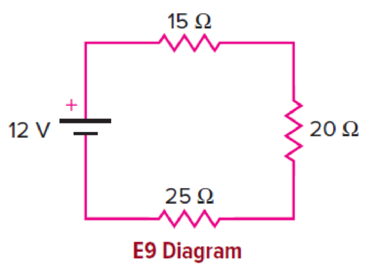
Three resistors are connected to a 12-V battery as shown. The internal resistance of the battery is negligible.
a. What is the total resistance in the circuit?
b. What is the current coming from the battery?
c. What is the current through the 15 Ω. resistance?
d. Does this same current flow through the 25 Ω resistance?
e. What is the voltage difference across the 20 Ω resistance?
(a)
The total resistance of the circuit.
Answer to Problem 9E
The equivalent resistance of the circuit is
Explanation of Solution
Given info: The voltage of the battery is
Write the formula for the equivalent resistance when three resistances are connected in series.
Here,
Substitute
Conclusion:
The equivalent resistance of the circuit is
(b)
The current in the circuit.
Answer to Problem 9E
The current in the circuit is
Explanation of Solution
Given info: The voltage of the battery is
Write the formula for the equivalent resistance when three resistances are connected in series.
Here,
Write the formula for the current in the circuit.
Here,
Substitute
Conclusion:
The current in the circuit is
(c)
The current through the resistor
Answer to Problem 9E
The current through the
Explanation of Solution
Given info: The voltage of the battery is
When resistors are connected in series, the path for current is same. So the current flowing through all the elements which are in series with each other is same.
In the given circuit, the three resistances are connected in series. So the current through each resistor will be same which will be equal to the current coming from the battery.
In the section (b), the current from the battery was found out to be
Conclusion:
The current through the
(d)
Whether the current flowing through
Answer to Problem 9E
The current flowing through
Explanation of Solution
Given info: The voltage of the battery is
When resistors are connected in series, the path for current is same. So the current flowing through all the elements which are in series with each other is same.
In the given circuit, the three resistances are connected in series. So the current through each resistor will be same which will be equal to the current coming from the battery.
Thus the current flowing through
Conclusion:
The current flowing through
(e)
The voltage across
Answer to Problem 9E
The voltage across
Explanation of Solution
Given info: The voltage of the battery is
Write the formula for the voltage across a resistor in series with two other resistors.
Here,
Substitute
Conclusion:
The voltage across
Want to see more full solutions like this?
Chapter 13 Solutions
PHYSICS OF EVERYDAY PHENOMENA >VALUE<


- A 1,00-?O voltmeter is placed in parallel with a 75.0kresistor in a circuit, (a) Draw a circuit diagram of the connection, (b) What is the resistance of the combination? If the voltage across the combination is kept the same as it was across the 75.0-kresistor alone, what is the percent increase in current? (d) If the current through the combination is kept the same as it was through the 75.0-kresistor alone, what is the percentage decrease in voltage? (e) Are the changes found in parts (c) and (d) significant? Discuss.arrow_forwardThree 100- resistors are connected as shown in Figure P28.5. The maximum power that can safely be delivered to any one resistor is 25.0 W. (a) What is the maximum potential difference that can be applied to the terminals a and b? (b) For the voltage determined in part (a), what is the power delivered to each resistor? (c) What is the total power delivered to the combination of resistors?arrow_forwardConsider the circuit shown in Figure P18.11. Find (a) the potential difference between points a and b and (b) the current in the 20.0- resistor. Figure P18.11arrow_forward
- . All of the electrical outlets in a room are connected in a single parallel circuit (Figure 7.38). The circuit is equipped with a 20-A fuse, and the voltage is 120 V. (a) What is the maximum total power that can be supplied by the outlets without blowing the fuse? (b) How many 1,200-W appliances can be plugged into the sockets without blowing the fuse?arrow_forwardUnreasonable Results A 1.58-V alkaline cell with a 0.200- internal resistance is supplying 8.50 A to a load, {a) What is its terminal voltage? (b) What is the value of the load resistance? (c) What is unreasonable about these results? (d) Which assumptions are unreasonable or inconsistent?arrow_forwardThe circuit in Figure P27.34a consists of three resistors and one battery with no internal resistance. (a) Find the current in the 5.00- resistor. (b) Find the power delivered to the 5.00- resistor. (c) In each of the circuits in Figures P27.34b, P27.34c, and P27.34d, an additional 15.0-V battery has been inserted into the circuit. Which diagram or diagrams represent a circuit that requires the use of Kirchhoffs rules to find the currents? Explain why. (d) In which of these three new circuits is the smallest amount of power delivered to the 10.0- resistor? (You need not calculate the power in each circuit if you explain your answer.) Figure P27.34arrow_forward
- Electric circuits are sometimes explained using a conceptual model of water flowing through a pipe. In this conceptual model, the voltage source is represented as a pump that pumps water through pipes and the pipes connect components in the circuit. Is a conceptual model of water flowing through a pipe an adequate representation of the circuit? How are electrons and wires similar to water molecules and pipes? How are they different?arrow_forwardFor the circuit shown in Figure P28.24, calculate (a) the current in the 2.00-11 resistor and (b) the potential difference between points a and b.arrow_forwardA potential difference of 12 V is found to produce a current of 0.40 A in a 3.2-m length of wire with a uniform radius of 0.40 cm. What is (a) the resistance of the wire? (b) The resistivity of the wire?arrow_forward
- The rather simple circuit shown below is known as a voltage divider. The symbol consisting of three horizontal lines is represents “ground” and can be defined as the point where the potential is zero. The voltage divider is widely used in circuits and a single voltage source can be used to provide reduced voltage to a load resistor as shown in the second part of the figure, (a) What is the output voltage Vout of circuit (a) in terms of R1,R2,andVin (b) What is the output voltage Vout of circuit (b) in terms of R1,R2,RLandVinarrow_forwardIntegrated Concepts (a) What is the average power output of a heart defibrillator that dissipates 400 J of energy in 10.0 ms? (b) Considering the high-power output, why doesn’t the defibrillator produce serious burns?arrow_forwardGiven a battery, an assortment of resistors, and a variety of voltage and current measuring devices, describe how you would determine the internal resistance of the battery.arrow_forward

 Physics for Scientists and Engineers, Technology ...PhysicsISBN:9781305116399Author:Raymond A. Serway, John W. JewettPublisher:Cengage Learning
 College PhysicsPhysicsISBN:9781938168000Author:Paul Peter Urone, Roger HinrichsPublisher:OpenStax College
 Physics for Scientists and Engineers with Modern ...PhysicsISBN:9781337553292Author:Raymond A. Serway, John W. JewettPublisher:Cengage Learning
 Physics for Scientists and EngineersPhysicsISBN:9781337553278Author:Raymond A. Serway, John W. JewettPublisher:Cengage Learning