
EBK STATICS AND MECHANICS OF MATERIALS
5th Edition
ISBN: 8220102955295
Author: HIBBELER
Publisher: PEARSON
expand_more
expand_more
format_list_bulleted
Concept explainers
Videos
Textbook Question
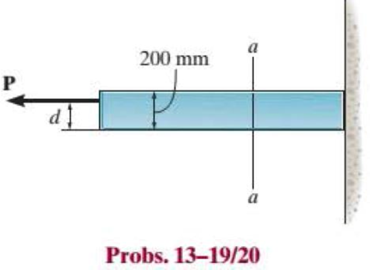
Chapter 13.2, Problem 19P
Determine the maximum distance d to the edge of the plate at which the force P can be applied so that it produces no compressive stresses on the plate at section a–a.The plate has a thickness of 20 mm and P acts along the centerline of this thickness.
Expert Solution & Answer
Want to see the full answer?
Check out a sample textbook solution
Students have asked these similar questions
Determine the shortest distance d to the edge of the plate at which the force P can be applied so that it produces no compressive stresses in the plate at section a–a. The plate has a thickness of 10 mm and P acts along the centerline of this thickness.
The plate has a thickness of 20 mm and width s = 260 mm. Force P acts along the centerline of this thickness.
Determine the maximum distance d at which the force P can be applied so that it produces no compressive stresses on the plate at section a-a.
The plate has a thickness of 20 mm and the force P = 3 kN acts along the centerline of this thickness such that d = 150 mm. Plot the distribution of normal stress acting along section a–a.
Chapter 13 Solutions
EBK STATICS AND MECHANICS OF MATERIALS
Ch. 13.1 - A spherical gas tank has an inner radius of r =...Ch. 13.1 - A pressurized spherical tank is made of...Ch. 13.1 - The thin-walled cylinder can be supported in one...Ch. 13.1 - Prob. 4PCh. 13.1 - Prob. 5PCh. 13.1 - Determine the maximum force P that can be exerted...Ch. 13.1 - Prob. 7PCh. 13.1 - The steel water pipe has an inner diameter of 12...Ch. 13.1 - The steel water pipe has an inner diameter of 12...Ch. 13.1 - The A-36-steel band is 2 in. wide and is secured...
Ch. 13.1 - The gas pipe line is supported every 20 ft by...Ch. 13.1 - Prob. 12PCh. 13.1 - An A-36-steel hoop has an inner diameter of 23.99...Ch. 13.1 - The ring, having the dimensions shown, is placed...Ch. 13.1 - Prob. 15PCh. 13.1 - Prob. 16PCh. 13.1 - Prob. 17PCh. 13.2 - In each case, determine the internal loadings that...Ch. 13.2 - The internal loadings act on the section. Show the...Ch. 13.2 - Determine the normal stress at comers A and B of...Ch. 13.2 - Determine the state of stress at point A on the...Ch. 13.2 - Determine the state of stress at point A on the...Ch. 13.2 - Determine the magnitude of the load P that will...Ch. 13.2 - Prob. 5FPCh. 13.2 - Determine the state of stress at point A on the...Ch. 13.2 - Determine the state of stress at point A on the...Ch. 13.2 - Determine the state of stress at point A on the...Ch. 13.2 - Determine the shortest distance d to the edge of...Ch. 13.2 - Determine the maximum distance d to the edge of...Ch. 13.2 - The plate has a thickness of 20 mm and the force P...Ch. 13.2 - If the load has a weight of 600 lb, determine the...Ch. 13.2 - The steel bracket is used to connect the ends of...Ch. 13.2 - Prob. 23PCh. 13.2 - The column is built up by gluing the two boards...Ch. 13.2 - Prob. 25PCh. 13.2 - The screw of the clamp exerts a compressive force...Ch. 13.2 - Prob. 27PCh. 13.2 - Prob. 28PCh. 13.2 - The joint is subjected to the force system shown....Ch. 13.2 - Prob. 30PCh. 13.2 - The 12-in.-diameter holt hook is subjected to the...Ch. 13.2 - Prob. 32PCh. 13.2 - Prob. 33PCh. 13.2 - Prob. 34PCh. 13.2 - Prob. 35PCh. 13.2 - The drill is jammed in the wall and is subjected...Ch. 13.2 - The drill is jammed in the wall and is subjected...Ch. 13.2 - The frame supports the distributed load shown....Ch. 13.2 - Prob. 39PCh. 13.2 - The rod has a diameter of 40 mm. If it is...Ch. 13.2 - The rod has a diameter of 40 mm. If it is...Ch. 13.2 - The beveled gear is subjected to the loads shown....Ch. 13.2 - The beveled gear is subjected to the loads shown....Ch. 13.2 - Determine the normal-stress developed at points A...Ch. 13.2 - Sketch the normal-stress distribution acting over...Ch. 13.2 - Prob. 46PCh. 13.2 - The solid rod is subjected to the loading shown....Ch. 13.2 - Prob. 48PCh. 13.2 - Prob. 49PCh. 13.2 - The C-frame is used in a riveting machine. If the...Ch. 13.2 - Prob. 51PCh. 13.2 - The uniform sign has a weight of 1500 lb and is...Ch. 13.2 - The uniform sign has a weight of 1500 lb and is...Ch. 13 - The post has a circular cross section of radius c....Ch. 13 - The 20-kg drum is suspended from the hook mounted...Ch. 13 - The 20-kg drum is suspended from the hook mounted...Ch. 13 - Prob. 4RPCh. 13 - If the cross section of the femur at section aa...Ch. 13 - Prob. 6RPCh. 13 - Prob. 7RPCh. 13 - Prob. 8RP
Knowledge Booster


Learn more about
Need a deep-dive on the concept behind this application? Look no further. Learn more about this topic, mechanical-engineering and related others by exploring similar questions and additional content below.Similar questions
- The horizontal force of P = 80 KN acts at the end of the plate. The plate has a thickness of 10 mm and P acts along the centerline of this thickness such that d = 50 mm. Plot the distribution of normal stress acting along section a-a.arrow_forwardThe bent shaft is fixed in the wall at A. If a force F is applied at B (the force is acting on the plane parallel to the x-o-y plane). Take F = 54 N and 0 = 45°. 1. Determine the internal forces acting on the section containing points D and E 2. Determine the normal stress component acting at point E 3. Determine the shear stress component developed at point E 4. Draw the state of stress on a volume element (stress element) located at point E 5. Determine the principal stresses acting at point E by constructing Mohr's circle A 150 mm E 200 mm 30 mm 75 mm B Farrow_forwardThe vertical force P acts on the bottom of the plate having a negligible weight. Determine the shortest distance d to the edge of the plate at which it can be applied so that it produces no compressive stresses on the plate at section a-a. The plate has a thickness of 10 mm and P acts along the centerline of this thickness. a 200 mm- d 300 mm a 500 mmarrow_forward
- The box beam is subjected to the 26-kN force that is applied at the center of its width, 75 mm from each side. Determine the principal stresses at point A and show the results in an element located at this point. Use the shear formula to calculate the shear stress.arrow_forwardThe clamp presses the smooth surface at E when tightening the screw. If the tension in the bolt is 40 kN, determine the principal stress at points A and B and show the results on the elements located at each of these points. The cross-sectional area at A and B is shown in the adjacent figure. 300 mm 50 mm 30 mm 100 mm B 25 mm A 100 mm -50 mmarrow_forwardThe solid bar has a diameter of 50 mm. The two forces and the torque Tx are acting at the origin of the x-y-z coordinate system which is coincident with the centroid of the cross-section of the bar; the 1800 N force is acting in the y-z plane and torque T is acting about the x-axis. Determine the state of stress at points A and B, and show the respective stress components acting on differential elements located at these two points. {30 marks} 200 mm y 200 mm B. 1200 N T= 40 N.m 1800 Narrow_forward
- The solid bar has a diameter of 50 mm. The two forces and the torque Tx are acting at the origin of the x-y-z coordinate system which is coincident with the centroid of the cross-section of the bar; the 1800 N force is acting in the y-z plane and torque Tx is acting about the x-axis. Determine the state of stress at points A and B, and show the respective stress components acting on differential elements located at these two points. 200 mm/ y 200 mm 1200 N Tx = 40 N.m %3D 1800 Narrow_forwardThe bar has a 100 mm by 15 mm rectangular cross section. The allowable normal and shear stresses on inclined 66° surface a – a must be limited to 50 MPa and 35 MPa, respectively. Determine the 100 mm magnitude of the maximum axial force P that can be applied to the bar, and determine the actual normal and shear Try one stresses acting on inclined plane a – a.arrow_forwardThe plate has a width of 0.5 m. If the stress distribution at the support varies as shown, determine the force P applied to the plate and the distance d to where it is applied.arrow_forward
- Use Mohr’s circle to determine the principal stresses at the point. Also, find the corresponding orientation of the element with respect to the element shown.arrow_forwardThe wide-flange beam is subjected to the 50-kN force. Determine the principal stresses in the beam at point A located on the web at the bottom of the upper flange. Although it is not very accurate, use the shear formula tocalculate the shear stress.arrow_forwardThe small-block has a thickness of 0.5 in. If the stress distribution at the support developed by the load varies as shown, determine the force F applied to the block, and the distance d to where it is applied.arrow_forward
arrow_back_ios
SEE MORE QUESTIONS
arrow_forward_ios
Recommended textbooks for you
 Elements Of ElectromagneticsMechanical EngineeringISBN:9780190698614Author:Sadiku, Matthew N. O.Publisher:Oxford University Press
 Mechanics of Materials (10th Edition)Mechanical EngineeringISBN:9780134319650Author:Russell C. HibbelerPublisher:PEARSON
 Thermodynamics: An Engineering ApproachMechanical EngineeringISBN:9781259822674Author:Yunus A. Cengel Dr., Michael A. BolesPublisher:McGraw-Hill Education
 Control Systems EngineeringMechanical EngineeringISBN:9781118170519Author:Norman S. NisePublisher:WILEY
 Mechanics of Materials (MindTap Course List)Mechanical EngineeringISBN:9781337093347Author:Barry J. Goodno, James M. GerePublisher:Cengage Learning
 Engineering Mechanics: StaticsMechanical EngineeringISBN:9781118807330Author:James L. Meriam, L. G. Kraige, J. N. BoltonPublisher:WILEY
Elements Of Electromagnetics
Mechanical Engineering
ISBN:9780190698614
Author:Sadiku, Matthew N. O.
Publisher:Oxford University Press
Mechanics of Materials (10th Edition)
Mechanical Engineering
ISBN:9780134319650
Author:Russell C. Hibbeler
Publisher:PEARSON
Thermodynamics: An Engineering Approach
Mechanical Engineering
ISBN:9781259822674
Author:Yunus A. Cengel Dr., Michael A. Boles
Publisher:McGraw-Hill Education
Control Systems Engineering
Mechanical Engineering
ISBN:9781118170519
Author:Norman S. Nise
Publisher:WILEY
Mechanics of Materials (MindTap Course List)
Mechanical Engineering
ISBN:9781337093347
Author:Barry J. Goodno, James M. Gere
Publisher:Cengage Learning
Engineering Mechanics: Statics
Mechanical Engineering
ISBN:9781118807330
Author:James L. Meriam, L. G. Kraige, J. N. Bolton
Publisher:WILEY
EVERYTHING on Axial Loading Normal Stress in 10 MINUTES - Mechanics of Materials; Author: Less Boring Lectures;https://www.youtube.com/watch?v=jQ-fNqZWrNg;License: Standard YouTube License, CC-BY