
Applied Statics and Strength of Materials (6th Edition)
6th Edition
ISBN: 9780133840728
Author: Limbrunner
Publisher: PEARSON
expand_more
expand_more
format_list_bulleted
Videos
Textbook Question
Chapter 14, Problem 14.38SP
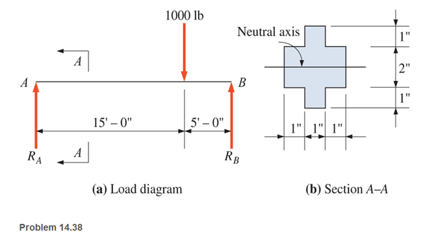
A simply supported beam with a cruciform cross section is loaded as shown. Calculate the maximum horizontal shear stress. Neglect the weight of the beam, (Hint: Check two planes in the cross section.)
Expert Solution & Answer
Want to see the full answer?
Check out a sample textbook solution
Students have asked these similar questions
For the beam shown, find the reactions at the supports and plot the shear-force and bending-moment diagrams. Label the diagrams properly and provide values at all key points.
A simply supported beam of hollow rectangular cross section is 100mm deep and 60mm wide with a wall thickness of 10mm. The beam has a span of 6m and carries a load as shown . Neglecting the weight of the beam draw a bending moment diagram and calculate the maximum bending moment. And determine the maximum bending stress in the material.
find moment at fixed end for Fixed-simply supported rectangular beam when 500N load is applied.
[Carefully solve]
Chapter 14 Solutions
Applied Statics and Strength of Materials (6th Edition)
Ch. 14 - Calculate the section modulus for: (a) a 6 -in-by-...Ch. 14 - Calculate the section modulus (with respect to the...Ch. 14 - Prob. 14.3PCh. 14 - Rework Problem 14.3 changing the orientation of...Ch. 14 - Assume that the timber member (a) of Problem 14.2...Ch. 14 - The structural steel built-up member (b) of...Ch. 14 - A round steel rod, 25 mm in diameter, is subjected...Ch. 14 - A square steel bar, 38 mm on each side, is used as...Ch. 14 - Calculate the moment strength for a W36302...Ch. 14 - Calculate the allowable bending moment for a solid...
Ch. 14 - The beams of cross sections shown are subjected to...Ch. 14 - A solid rectangular simply supported timber beam 6...Ch. 14 - A W1430 supports the loads shown. Calculate the...Ch. 14 - If the allowable shear stress is 100 MPa,...Ch. 14 - A steel pin 112 in diameter is subjected to a...Ch. 14 - A timber power-line pole is 10 in. in diameter at...Ch. 14 - Calculate the value of S and Z and the shape...Ch. 14 - For beams that have cross sections as shown for...Ch. 14 - Calculate the maximum load P that the beam shown...Ch. 14 - A 412 (S4S) hem-fir timber beam carries a...Ch. 14 - A simply supported W1636 A992 steel beam carries a...Ch. 14 - A W250115 steel wide-flange section supports a...Ch. 14 - Assume that the floor joist dimensions of Example...Ch. 14 - Calculate the allowable superimposed uniformly...Ch. 14 - A 3 -in.-by- 12 -in. (S4S) scaffold timber plank...Ch. 14 - For the following computer problems, any...Ch. 14 - For the following computer problems, any...Ch. 14 - For the following computer problems, any...Ch. 14 - Calculate the section modulus with respect to the...Ch. 14 - The timber box section (a) of Problem 14.29 is...Ch. 14 - A timber beam is subjected to a maximum bending...Ch. 14 - Rework Problem 14.31 assuming that the beam is...Ch. 14 - A 12 -in.-diameter steel rod projects 2 ft...Ch. 14 - Calculate the maximum bending stress in a W530101...Ch. 14 - A cantilever cast-iron beam is 6 ft long and has a...Ch. 14 - 14.36 Calculate the moment strength for a...Ch. 14 - A W813 steel wide-flange beam on a 20 -ft span is...Ch. 14 - A simply supported beam with a cruciform cross...Ch. 14 - A rectangular beam 100 mm in width and 250 mm in...Ch. 14 - The timber box section (a) of Problem 14.29 is...Ch. 14 - For the I-shaped timber beam shown, calculate the...Ch. 14 - 14.42 A steel wide-flange beam is oriented so that...Ch. 14 - A W1045steel wide-flange beam supports a uniformly...Ch. 14 - 14.44 A steel wide-flange section is subjected to...Ch. 14 - A W30108 steel wide-flange beam is simply...Ch. 14 - A W612 is strengthened with a 34 -in.-by- 34 -in....Ch. 14 - Four wood boards 1 in. by 6 in. in cross section...Ch. 14 - A lintel consists of two 8 -in.-by- 12 in. steel...Ch. 14 - A 50 -mm-by- 300 -mm scaffold timber plank, placed...Ch. 14 - A laminated wood beam is built up by gluing...Ch. 14 - A rectangular hollow shape carries loads as shown....Ch. 14 - For the beam shown, calculate the maximum tensile...Ch. 14 - 14.53 A box beam is built up of four -in.-by--in....Ch. 14 - 14.54 Find the value of the loads P that can be...Ch. 14 - 14.55 Solve Problem 14.54 assuming that the timber...Ch. 14 - Calculate the values of S and Z and the shape...Ch. 14 - 14.57 A is supported on simple supports on a -ft...
Knowledge Booster


Learn more about
Need a deep-dive on the concept behind this application? Look no further. Learn more about this topic, mechanical-engineering and related others by exploring similar questions and additional content below.Similar questions
- -15 A composite beam is constructed froma wood beam (3 in. x 6 in.) and a steel plate (3 in, wide). The wood and the steel are securely fastened to act as a single beam. The beam is subjected to a positive bending moment M. = 75 kip-in. Calculate the required thickness of the steel plate based on the following limit states: Allowable compressive stress in the wood = 2 ksi Allowable tensile stress in the wood = 2 ksi Allowable tensile stress in the steel plate = 16 ksi Assume that Ew= 1,500 ksi and es= 30,000 ksi.arrow_forwardFor the beam shown, find the reactions at the supports and plot the shear-force and bending-moment diagrams. Label the diagrams properly and provide values at all key points within the diagrams.arrow_forwardCalculate the modulus of section of rectangle beam of breadth 120 mm and height 200 mm.arrow_forward
- For the beam shown below, the distributed load along AB is a= 6 kN/m, the concentrated load at Point C is b = 10 kN. Draw FBD, sove for reaction forces, then draw shear & momment diagram. Input the internal bending moment at the cross-section from Point B: ____ kN m. Input the negative sign "-" if it is negative, and calculate your answer to 1 decimal place.arrow_forwardA cantileve beam is loaded with uniformly distributed load of kips/ft, as shown in figure below. By double integration:arrow_forward1.Calculate the 2nd moment of area for a beam with a length of 200 mm, a width of 20 mm and a height of 3 mm. 2. For the same beam, and using the provided equations, calculate the maximum deflection if the beam was cantilevered, had a Young's modulus of 207 GPa and had a load of 2.5 N applied at the free end.arrow_forward
- A cantilevered beam is loaded with a uniformly distributed load as shown below. If w1 = 2000 lb/ft, what is the value of the moment (ft-lb) at x = 2 ft?(NEED NEAT HANDWRITTEN SOLUTION ONLY OTHERWISE DOWNVOTE)arrow_forwardA steel bar 140mm diameter is used to support a pulley block.if the bar is simply supported over a span of 1.4m, calculate the maximum bending stress in the material when the pulley block is at mid span supporting a load of 24KNarrow_forwardA 4-m long simply supported beam has a section modulus of 1408 x 10³ mm³. The allowable stress in the beam is not to exceed 100MPa. The maximum distributed load that the beam can carry is most nearly,arrow_forward
- A brass strip, 50 mm x 12 mm in section, is riveted to a steel strip, Figure (22) 65 mm x 10 mm in section, to form a compound beam of total depth 22 mm, the brass strip being on top and the beam section being symmetrical about the vertical axis. The beam is simply supported on a span of 1.3 m and carries a load of 2 kN at mid-span. (a) Determine the maximum stresses in each of the materials owing to bending. (b) Make a diagram showing the distribution of bending stress over the depth of the beam. Take E for steel = 200 GN/m² and E for brass = 100 GN/m². Ans.( 0) = 130 MN/m²; 0, = 162.9 MN/m²]arrow_forwardA beam with the cross-section shown is carrying a bending moment of M. Calculate the maximum bending stress (σ) in the beam.arrow_forwardFigure shows a composite beam having a symmetry trapezium cross-section compromised of steel and brass being subjected to bending moment. Using the data given in Table, and factor of safety of 3.5, determine the largest bending moment M which can be applied to the composite beam when it is being bent about x-axis.arrow_forward
arrow_back_ios
SEE MORE QUESTIONS
arrow_forward_ios
Recommended textbooks for you
 Mechanics of Materials (MindTap Course List)Mechanical EngineeringISBN:9781337093347Author:Barry J. Goodno, James M. GerePublisher:Cengage Learning
Mechanics of Materials (MindTap Course List)
Mechanical Engineering
ISBN:9781337093347
Author:Barry J. Goodno, James M. Gere
Publisher:Cengage Learning
Mechanics of Materials Lecture: Beam Design; Author: UWMC Engineering;https://www.youtube.com/watch?v=-wVs5pvQPm4;License: Standard Youtube License