
Applied Statics and Strength of Materials (6th Edition)
6th Edition
ISBN: 9780133840544
Author: George F. Limbrunner, Craig D'Allaird, Leonard Spiegel
Publisher: PEARSON
expand_more
expand_more
format_list_bulleted
Concept explainers
Videos
Textbook Question
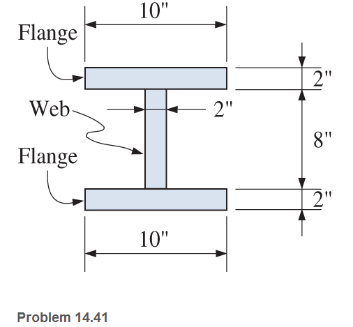
Chapter 14, Problem 14.41SP
For the I-shaped timber beam shown, calculate the maximum vertical shear force that will induce a maximum horizontal shear stress of
Expert Solution & Answer
Want to see the full answer?
Check out a sample textbook solution
Students have asked these similar questions
For the beam shown, find the reactions at the supports and plot the shear-force and bending-moment diagrams. Label the diagrams properly and provide values at all key points.
A simply supported beam of hollow rectangular cross section is 100mm deep and 60mm wide with a wall thickness of 10mm. The beam has a span of 6m and carries a load as shown . Neglecting the weight of the beam draw a bending moment diagram and calculate the maximum bending moment. And determine the maximum bending stress in the material.
Calculate the modulus of section of rectangle beam of breadth 120 mm and height 200 mm.
Chapter 14 Solutions
Applied Statics and Strength of Materials (6th Edition)
Ch. 14 - Calculate the section modulus for: (a) a 6 -in-by-...Ch. 14 - Calculate the section modulus (with respect to the...Ch. 14 - Prob. 14.3PCh. 14 - Rework Problem 14.3 changing the orientation of...Ch. 14 - Assume that the timber member (a) of Problem 14.2...Ch. 14 - The structural steel built-up member (b) of...Ch. 14 - A round steel rod, 25 mm in diameter, is subjected...Ch. 14 - A square steel bar, 38 mm on each side, is used as...Ch. 14 - Calculate the moment strength for a W36302...Ch. 14 - Calculate the allowable bending moment for a solid...
Ch. 14 - The beams of cross sections shown are subjected to...Ch. 14 - A solid rectangular simply supported timber beam 6...Ch. 14 - A W1430 supports the loads shown. Calculate the...Ch. 14 - If the allowable shear stress is 100 MPa,...Ch. 14 - A steel pin 112 in diameter is subjected to a...Ch. 14 - A timber power-line pole is 10 in. in diameter at...Ch. 14 - Calculate the value of S and Z and the shape...Ch. 14 - For beams that have cross sections as shown for...Ch. 14 - Calculate the maximum load P that the beam shown...Ch. 14 - A 412 (S4S) hem-fir timber beam carries a...Ch. 14 - A simply supported W1636 A992 steel beam carries a...Ch. 14 - A W250115 steel wide-flange section supports a...Ch. 14 - Assume that the floor joist dimensions of Example...Ch. 14 - Calculate the allowable superimposed uniformly...Ch. 14 - A 3 -in.-by- 12 -in. (S4S) scaffold timber plank...Ch. 14 - For the following computer problems, any...Ch. 14 - For the following computer problems, any...Ch. 14 - For the following computer problems, any...Ch. 14 - Calculate the section modulus with respect to the...Ch. 14 - The timber box section (a) of Problem 14.29 is...Ch. 14 - A timber beam is subjected to a maximum bending...Ch. 14 - Rework Problem 14.31 assuming that the beam is...Ch. 14 - A 12 -in.-diameter steel rod projects 2 ft...Ch. 14 - Calculate the maximum bending stress in a W530101...Ch. 14 - A cantilever cast-iron beam is 6 ft long and has a...Ch. 14 - 14.36 Calculate the moment strength for a...Ch. 14 - A W813 steel wide-flange beam on a 20 -ft span is...Ch. 14 - A simply supported beam with a cruciform cross...Ch. 14 - A rectangular beam 100 mm in width and 250 mm in...Ch. 14 - The timber box section (a) of Problem 14.29 is...Ch. 14 - For the I-shaped timber beam shown, calculate the...Ch. 14 - 14.42 A steel wide-flange beam is oriented so that...Ch. 14 - A W1045steel wide-flange beam supports a uniformly...Ch. 14 - 14.44 A steel wide-flange section is subjected to...Ch. 14 - A W30108 steel wide-flange beam is simply...Ch. 14 - A W612 is strengthened with a 34 -in.-by- 34 -in....Ch. 14 - Four wood boards 1 in. by 6 in. in cross section...Ch. 14 - A lintel consists of two 8 -in.-by- 12 in. steel...Ch. 14 - A 50 -mm-by- 300 -mm scaffold timber plank, placed...Ch. 14 - A laminated wood beam is built up by gluing...Ch. 14 - A rectangular hollow shape carries loads as shown....Ch. 14 - For the beam shown, calculate the maximum tensile...Ch. 14 - 14.53 A box beam is built up of four -in.-by--in....Ch. 14 - 14.54 Find the value of the loads P that can be...Ch. 14 - 14.55 Solve Problem 14.54 assuming that the timber...Ch. 14 - Calculate the values of S and Z and the shape...Ch. 14 - 14.57 A is supported on simple supports on a -ft...
Knowledge Booster


Learn more about
Need a deep-dive on the concept behind this application? Look no further. Learn more about this topic, mechanical-engineering and related others by exploring similar questions and additional content below.Similar questions
- A simply supported beam 10 m long has an overhang of 1.1 m at the left support. If a highway uniform load of 12.02 kN/m and a concentrated load of 194 kN, passes thru the beam, compute the maximum positive shear (kN) based on influence line for maximum shear at mid span.arrow_forwardCalculate the normal stress, shear stress, and bending deformation of the beam. (Point A has a pinned support, while point C has a roller support)arrow_forwardSolve the following questions: Plot the shear and moment diagrams for the beam loaded with both distributed and point loads. What is the value of the shear at x = 0 m?arrow_forward
- A beam with the cross-section shown is carrying a bending moment of M. Calculate the maximum bending stress (σ) in the beam.arrow_forwardA timber dam is made of planking backed by vertical piles. The piles are built-in at the section A where they enter the ground and they are supported by horizontal struts whose center lines are 10 m above A. The piles are spaced 1 m apart between centers and the depth of water against the dam is 10 m. Assuming that the thrust in the strut is two-sevenths the total water pressure resisted by each pile, sketch the form of the bending moment and shearing force diagrams for a pile. Determine the magnitude of the bending moment at A and the position of the section which is free from bending moment. (Cambridge). i. 238 kN-m; 0.75 m from A. ii. 238 kN-m; 0.75 m from B.arrow_forwardDraw the free body diagram, shear force diagram, and bending moment diagram for the beam shown below and calculate values at each point:arrow_forward
- For the beam shown, derive the expressions for V and M, and draw the shear force and bending moment diagrams. Calculate the shear force V and bending moment M at a cross section located 0.5 m from the fixed support. Neglect the weight of the beam. (Show complete calculation and step by step process. Show free body diagram)arrow_forwardA beam of I section 200 mm wide and 300mm deep with flange and web thickness 20 mm is used as a simply supported beam over a span of 7 m.the beam carries a distributed load of 5 kn/m over the whole span and a concentrated load of 20 kn at mid span determine the maximum bending stress set up and sketch the stress distribution.arrow_forwardA beam 8 m span is freely supported at its ends and a udl of 40 KN/m is spread over the whole span of the heam. In addition a concentrated load of 150 KN is applied at a distance of 3 m from the left support. The section of the beam is 200 mm wide and 400 mm deep. Find the maximum bending stress induced in the beam section.arrow_forward
- The wood beam with an overhang of b = 6 ft carries a concentrated load P and a uniformly distributed load of intensity w0. If the working stress for wood in bending is 1200 psi, find the maximum values of P and wo that can be applied simultaneously.arrow_forwardA horizontal beam under bending has a maximum bending stress of 100 MpA and a maximum shear stress of 20 Mpa. What is the maximum principal stress induced in the beam.arrow_forwardCalculate the maximum shear force at support and the maximum bending momentarrow_forward
arrow_back_ios
SEE MORE QUESTIONS
arrow_forward_ios
Recommended textbooks for you
 Mechanics of Materials (MindTap Course List)Mechanical EngineeringISBN:9781337093347Author:Barry J. Goodno, James M. GerePublisher:Cengage Learning
Mechanics of Materials (MindTap Course List)
Mechanical Engineering
ISBN:9781337093347
Author:Barry J. Goodno, James M. Gere
Publisher:Cengage Learning
Understanding Shear Force and Bending Moment Diagrams; Author: The Efficient Engineer;https://www.youtube.com/watch?v=C-FEVzI8oe8;License: Standard YouTube License, CC-BY
Bending Stress; Author: moodlemech;https://www.youtube.com/watch?v=9QIqewkE6xM;License: Standard Youtube License