
Applied Statics and Strength of Materials (6th Edition)
6th Edition
ISBN: 9780133840544
Author: George F. Limbrunner, Craig D'Allaird, Leonard Spiegel
Publisher: PEARSON
expand_more
expand_more
format_list_bulleted
Videos
Textbook Question
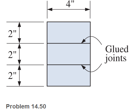
Chapter 14, Problem 14.50SP
A laminated wood beam is built up by gluing together three
(a) Calculate the maximum allowable load P that can be applied at the free end.
(b) Calculate the maximum bending stress in the beam.
Expert Solution & Answer
Want to see the full answer?
Check out a sample textbook solution
Students have asked these similar questions
a rectangular beam with a span of 20ft is simply supported at both ends. The maximum flexural stress for the beam is 1200 psi and the dimensions of its cross-section are: b=4 in and h=10 in. If the beam is to be loaded at mid-span with a concentrated load of 2000lbs, will the beam collapse?
A 4-m long simply supported beam has a section modulus of 1408 x 10³ mm³. The allowable stress in the beam is not to exceed 100MPa. The maximum distributed load that the beam can carry is most nearly,
A circular solid cross-section cantilever is fixed at one end and bears a concentrated load P at the other. Over a 2m length, the diameter increases uniformly from 200 mm at the free end to 400 mm at the fixed end. At what distance from the free end will the bending stress in the cantilever be maximum? If the concentrated load P=30 KN, what is the maximum bending stress
Chapter 14 Solutions
Applied Statics and Strength of Materials (6th Edition)
Ch. 14 - Calculate the section modulus for: (a) a 6 -in-by-...Ch. 14 - Calculate the section modulus (with respect to the...Ch. 14 - Prob. 14.3PCh. 14 - Rework Problem 14.3 changing the orientation of...Ch. 14 - Assume that the timber member (a) of Problem 14.2...Ch. 14 - The structural steel built-up member (b) of...Ch. 14 - A round steel rod, 25 mm in diameter, is subjected...Ch. 14 - A square steel bar, 38 mm on each side, is used as...Ch. 14 - Calculate the moment strength for a W36302...Ch. 14 - Calculate the allowable bending moment for a solid...
Ch. 14 - The beams of cross sections shown are subjected to...Ch. 14 - A solid rectangular simply supported timber beam 6...Ch. 14 - A W1430 supports the loads shown. Calculate the...Ch. 14 - If the allowable shear stress is 100 MPa,...Ch. 14 - A steel pin 112 in diameter is subjected to a...Ch. 14 - A timber power-line pole is 10 in. in diameter at...Ch. 14 - Calculate the value of S and Z and the shape...Ch. 14 - For beams that have cross sections as shown for...Ch. 14 - Calculate the maximum load P that the beam shown...Ch. 14 - A 412 (S4S) hem-fir timber beam carries a...Ch. 14 - A simply supported W1636 A992 steel beam carries a...Ch. 14 - A W250115 steel wide-flange section supports a...Ch. 14 - Assume that the floor joist dimensions of Example...Ch. 14 - Calculate the allowable superimposed uniformly...Ch. 14 - A 3 -in.-by- 12 -in. (S4S) scaffold timber plank...Ch. 14 - For the following computer problems, any...Ch. 14 - For the following computer problems, any...Ch. 14 - For the following computer problems, any...Ch. 14 - Calculate the section modulus with respect to the...Ch. 14 - The timber box section (a) of Problem 14.29 is...Ch. 14 - A timber beam is subjected to a maximum bending...Ch. 14 - Rework Problem 14.31 assuming that the beam is...Ch. 14 - A 12 -in.-diameter steel rod projects 2 ft...Ch. 14 - Calculate the maximum bending stress in a W530101...Ch. 14 - A cantilever cast-iron beam is 6 ft long and has a...Ch. 14 - 14.36 Calculate the moment strength for a...Ch. 14 - A W813 steel wide-flange beam on a 20 -ft span is...Ch. 14 - A simply supported beam with a cruciform cross...Ch. 14 - A rectangular beam 100 mm in width and 250 mm in...Ch. 14 - The timber box section (a) of Problem 14.29 is...Ch. 14 - For the I-shaped timber beam shown, calculate the...Ch. 14 - 14.42 A steel wide-flange beam is oriented so that...Ch. 14 - A W1045steel wide-flange beam supports a uniformly...Ch. 14 - 14.44 A steel wide-flange section is subjected to...Ch. 14 - A W30108 steel wide-flange beam is simply...Ch. 14 - A W612 is strengthened with a 34 -in.-by- 34 -in....Ch. 14 - Four wood boards 1 in. by 6 in. in cross section...Ch. 14 - A lintel consists of two 8 -in.-by- 12 in. steel...Ch. 14 - A 50 -mm-by- 300 -mm scaffold timber plank, placed...Ch. 14 - A laminated wood beam is built up by gluing...Ch. 14 - A rectangular hollow shape carries loads as shown....Ch. 14 - For the beam shown, calculate the maximum tensile...Ch. 14 - 14.53 A box beam is built up of four -in.-by--in....Ch. 14 - 14.54 Find the value of the loads P that can be...Ch. 14 - 14.55 Solve Problem 14.54 assuming that the timber...Ch. 14 - Calculate the values of S and Z and the shape...Ch. 14 - 14.57 A is supported on simple supports on a -ft...
Knowledge Booster


Learn more about
Need a deep-dive on the concept behind this application? Look no further. Learn more about this topic, mechanical-engineering and related others by exploring similar questions and additional content below.Similar questions
- A pontoon bridge (see figure) is constructed of two longitudinal wood beams, known as bulks, that span between adjacent pontoons and support the transverse floor beams, which arc called chesses. For purposes of design, assume that a uniform floor load of 7.5 kPa acts over the chesses. (This load includes an allowance for the weights of the chesses and balks.) Also, assume that the chesses are 2.5 m long and that the balks are simply supported with a span of 3.0 m. The allowable bending stress in the wood is 15 MPa. If the balks have a square cross section, what is their minimum required width b^l Repeat part (a) if the balk width is 1.5 b and the balk depth is b; compare the cross-sectional areas of the two designs.arrow_forwardA two-axle carriage that is part of an over head traveling crane in a testing laboratory moves slowly across a simple beam AB (sec figure). The load transmitted to the beam from the front axle is 2200 lb and from the rear axle is 3800 lb. The weight of the beam itself may be disregarded. Determine the minimum required section modulus S for the beam if the allowable bending stress is 17,0 ksi, the length of the beam is 18 ft, and the wheelbase of the carriage is 5 ft. Select the most economical I-beam (S shape) from Table F-2(a), Appendix F.arrow_forwardA hollow box beam is constructed with webs of Douglas-fir plywood and flanges of pine, as shown in the figure in a cross-sectional view. The plywood is 1 in. thick and 12 in. wide; the flanges are 2 in. × 4 in. (nominal size). The modulus of elasticity for the plywood is 1,800,000 psi and for the pine is 1,400,000 psi. If the allowable stresses are 2000 psi for the plywood and 1750 psi for the pine, find the allowable bending moment Mmaxwhen the beam is bent about the z axis. Repeat part (a) if the beam is now bent about its y-axis.arrow_forward
- -15 A composite beam is constructed froma wood beam (3 in. x 6 in.) and a steel plate (3 in, wide). The wood and the steel are securely fastened to act as a single beam. The beam is subjected to a positive bending moment M. = 75 kip-in. Calculate the required thickness of the steel plate based on the following limit states: Allowable compressive stress in the wood = 2 ksi Allowable tensile stress in the wood = 2 ksi Allowable tensile stress in the steel plate = 16 ksi Assume that Ew= 1,500 ksi and es= 30,000 ksi.arrow_forwardThe wood joists supporting a plank Floor (see figure) are 38 mm × 220 mm in cross section (actual dimensions) and have a span length of L = 4.0 m. The floor load is 5.0 kPa, which includes the weight of the joists and the floor. (a) Calculate the maximum permissible spacing s of the joists if the allowable bending stress is 14 M Pa. (Assume that each joist may be represented as a simple beam carrying a uniform load.) (b) If spacing s = 406 mm, what is the required depth ft of the joist? Assume all other variables remain unchanged.arrow_forwardA weight W = 4000 lb falls through a height h = 0.5 in, onto the midpoint of a simple beam of length L = 10 ft (see figure). Assuming that the allowable bending stress in the beam is = 18,000 psi and E = 30 x 10* psi, select the lightest wide-flange beam listed in Table F-l(a) in Appendix F that will be satisfactory.arrow_forward
- A floor system in a small building consists of wood planks supported by 2-in. (nominal width) joists spaced at distance s and measured from center to center (see figure). The span length L of each joist is 12 ft, the spacing s of the joists is 16 in., and the allowable bending stress in the wood is 1250 psi. The uniform floor load is 120 lb/ft", which includes an allowance for the weight of the floor system itself. Calculate the required section modulus S for the joists, and then select a suitable joist size (surfaced lumber) from Appendix G, assuming that each joist may be represented as a simple beam carrying a uniform load. What is the maximum floor load that can be applied to your final beam selection in part (a)?arrow_forwardA box beam is constructed of four wood boards as shown in the figure part a. The webs are S in, x 1 irt and the flanges arc 6 in. X 1 in. boards (actual dimensions), joined by screws for which the allowable load in shear is F = 250 lb per screw. Calculate the maximum permissible longitudinal spacing ,vfflax of the screws if the shear force ^is 12001b. Repeat part (a) if the flanges arc attached to the webs using a horizontal arrangement of screws as shown in the figure part b.arrow_forwardSolve the preceding problem for a wide-flange beam with h = 404 mm, b = 140 mm, bf= 11.2 mm, and rf. = 6.99 mm.arrow_forward
- A cantilever beam is subjected to a concentrated load of 2000N. The cross sectional dimensions of the double-tee beam are shown. Determine (a) the shear stress at point H, which is 17 mm below the centroid of the double-tee shape, (b) the shear stress at point K, which is 5 mm above the centroid of the double tee shape, and (c) the maximum horisontal shear stress in the double tee shape.arrow_forwardA floor system in a small building consistsof wood planks supported by 2-in. (nominal width)joists spaced at distance s and measured from centerto center (see figure). The span length L of eachjoist is 12 ft, the spacing s of the joists is 16 in., andthe allowable bending stress in the wood is 1250 psi.The uniform floor load is 120 lb/ft2, which includesan allowance for the weight of the floor system itself.(a) Calculate the required section modulus S for thejoists, and then select a suitable joist size (surfacedlumber) from Appendix G, assuming thateach joist may be represented as a simple beamcarrying a uniform load.(b) What is the maximum floor load that can beapplied to your final beam selection in part (a)?arrow_forwardA metal beam with span L =3 ft is simply supported at points A and B. The uniform load on the beam (including its own weight) is q =160 lb/in. The cross section of the beam is rectangular with width b =1 in. and height h =4 in. The beam is adequately supported against sideways buckling. Determine the bending stress in the top and bottom of the beam and maximum shear stress at the neutral axisarrow_forward
arrow_back_ios
SEE MORE QUESTIONS
arrow_forward_ios
Recommended textbooks for you
 Mechanics of Materials (MindTap Course List)Mechanical EngineeringISBN:9781337093347Author:Barry J. Goodno, James M. GerePublisher:Cengage Learning
Mechanics of Materials (MindTap Course List)
Mechanical Engineering
ISBN:9781337093347
Author:Barry J. Goodno, James M. Gere
Publisher:Cengage Learning
Mechanics of Materials Lecture: Beam Design; Author: UWMC Engineering;https://www.youtube.com/watch?v=-wVs5pvQPm4;License: Standard Youtube License