Concept explainers
Videos
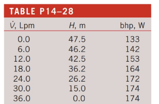
The performance data for a centrifugal water pump are shown in Table P14—28 for water at
(
(a)
The pump efficiency (percent) for each row.
Answer to Problem 28P
The pump efficiency for each row is tabulated below.
| | | | |
| | | | |
| | | | |
| | | | |
| | | | |
| | | | |
| | | | |
| | | | |
Explanation of Solution
Given information:
The performance data for a centrifugal water pump is tabulated which is shown in the following figure.
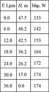
Figure-(I)
The figure shows the table containing the performance of a centrifugal pump with respect to its volume flow rate, head developed, and the power output.
Write the expression for the efficiency of the
Here, the density of the water is
Calculation:
Refer to Table A-3, “Properties of saturated water” to obtain the value of density
Substitute
Thus, the efficiency for the
Substitute
Thus, the efficiency for the
Substitute
Thus, the efficiency for the
Substitute
Thus, the efficiency for the
Substitute
Thus, the efficiency for the
Substitute
Thus, the efficiency for the
Substitute
Thus, the efficiency for the
Conclusion:
Tabulate the calculated efficiencies for each row.
| | | | |
| | | | |
| | | | |
| | | | |
| | | | |
| | | | |
| | | | |
| | | | |
(b)
The volume flow rate
Explanation of Solution
The best efficiency point (BEP) of the pump is obtained at the
Therefore, the volume flow rate is
Want to see more full solutions like this?
Chapter 14 Solutions
Fluid Mechanics Fundamentals And Applications


- A manufacturer of small water pumps lists the performance data for a family of its pumps as a parabolic curve fit, Havailable = H0 − aV.2 , where H0 is the pump’s shutoff head and a is a coefficient. Both H0 and a are listed in a table for the pump family, along with the pump’s free delivery. The pump head is given in units of feet of water column, and capacity is given in units of gallons per minute. (a) What are the units of coefficient a? (b) Generate an expression for the pump’s ree delivery V.max in terms of H0 and a. (c) Suppose one of the manufacturer’s pumps is used to pump water from one large reservoir to another at a igher elevation. The free surfaces of both reservoirs are exposed to atmospheric pressure. The system curve simplifies to Hrequired = (z2 − z1) + bV.2 Calculate the operating point of the pump (V. operating and Hoperating) in terms of H0, a, b, and elevation difference z2 − z1.arrow_forwardA centrifugal pump delivers 25 liters of water per second against a head of 10 meters and running at 1300 rpm requires 10 kW of power. Determine the discharge, head of the pump and power required if the pump runs at 1500 rpm. (Ans. 0.0288cumec or 1.73 cu.m./min , 13.31m, 15.36kw)arrow_forwardHow is the specific speed used to predict hydraulic turbine performance?arrow_forward
- A pump has a head of 20m at 450rpm. What is the increase in head developed by the pump if speed increase to 1000rpm? ANSWER: 78.76 marrow_forwardIn the construction of pump troughs for accommodation of screw pumps, what is the construction method to ensure close contact between the screw pumps and the pump trough?arrow_forwardIn Fig. is shown a plot of pump net head as a function of pump volume flow rate, or capacity. On the figure, label the shutoff head, the free delivery, the pump performance curve, the system curve, and the operating point.arrow_forward
- A pump is designed to deliver 9500 L/min of water at a required head of 8 m. The pump shaft rotates at 1100 rpm. The pump specific speed in nondimensional form is (a) 0.277 (b) 0.515 (c) 1.17 (d ) 1.42 (e) 1.88arrow_forward1Two water pumps are arranged in series. The performance data for both pumps follow the parabolic curve fit Havailable =H0 =aV ^2. For pump 1, H0 =5.30 m and coefficient a =0.0438 m/Lpm^2; for pump 2, H0 =8.70 m and coefficient a =0.0347 m/Lpm^2. In either case, the units ofnet pump head H are m, and the units of capacity V are Lpm.Calculate the combined shutoff head. Complete Answer, thank youarrow_forwardThe diameter of the discharge pipe of pump is 15 cm and that of intake pipe is 20 cm. The pressure gage at discharge reads 257 kPa and a vacuum gage at intake reads 195mm Hg. The flow rate is 90000 L/min and the applied torque in the pump shaft is 6.5 kN.m for a mechanical efficiency is 88% determine a.) the pump used; b.) the pumps to be used for a four-parallel pump arrangement.arrow_forward
- 1. A hydroelectric plant has 20 MW generator with an efficiency of 96 %. The generatoris directly coupled to a vertical Francis type hydraulic turbine having an efficiency of 80%.The total gross head on the turbine is 150 m while the loss of head due to friction is 4 %of the gross head, the runaway is not to exceed 750 rpm. Determine the flow of waterthrough the turbine in m3/s. Complete Solution/s (i.e. transformations, equivalent formula, etc).arrow_forwardDiscuss which dimensionless pump performance parameter is typically used as the independent parameter. Repeat for turbines instead of pumps. Explain.arrow_forwardPAY ATTENTION TO THE QUESTION : What is the resulting flow rate in the system if three pumps are used in parallel? (a) 0.483 m^3/s (b) 0.364 m^3/s (c) 0.333 m^3/s (d) 0.563 m^3/s 1. The Head -flowrate curve for a centrifugal pump is given by: HP = 28 -30Q2 Where, HP is in meter and Q is in m3/s . This pump is used to pump water for a system with the following (H-Q) curve: HS = 8 + 150Q2 Where, HS is in meter and Q is in m3/s . IT SAYS : if theee pumps are used in parallel PAY ATTENTION Multiple choice choose correct answerarrow_forward
 Elements Of ElectromagneticsMechanical EngineeringISBN:9780190698614Author:Sadiku, Matthew N. O.Publisher:Oxford University Press
 Mechanics of Materials (10th Edition)Mechanical EngineeringISBN:9780134319650Author:Russell C. HibbelerPublisher:PEARSON
 Thermodynamics: An Engineering ApproachMechanical EngineeringISBN:9781259822674Author:Yunus A. Cengel Dr., Michael A. BolesPublisher:McGraw-Hill Education
 Control Systems EngineeringMechanical EngineeringISBN:9781118170519Author:Norman S. NisePublisher:WILEY
 Mechanics of Materials (MindTap Course List)Mechanical EngineeringISBN:9781337093347Author:Barry J. Goodno, James M. GerePublisher:Cengage Learning
 Engineering Mechanics: StaticsMechanical EngineeringISBN:9781118807330Author:James L. Meriam, L. G. Kraige, J. N. BoltonPublisher:WILEY