
Concept explainers
Videos
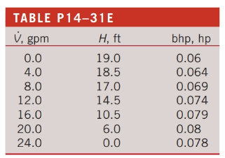
The performance data for a centrifugal water pump arc shown in Table P14—31E for water at
(a)
The centrifugal pump efficiency for each row.
Answer to Problem 31EP
The pimp efficiency for each row is tabulated below.
| | | | |
| | | | |
| | | | |
| | | | |
| | | | |
| | | | |
| | | | |
| | | | |
Explanation of Solution
Given information:
The performance data for a centrifugal water pump is tabulated which is shown in the following figure.
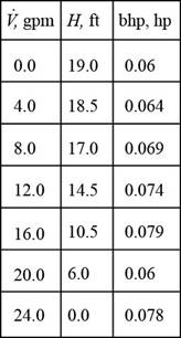
Figure-(I)
The figure shows the table containing the performance of a centrifugal pump with respect to its volume flow rate, head developed and the power output.
Write the expression for the efficiency of the
Here, the density of the water is
Write the formula for the interpolation of two variables.
Here, the density of the water is represented by the variable
Calculation:
Refer to Table A-3E, “Properties of saturated water” to obtain the values of
Prepare the table for pressure and temperature.
| Temperature, | Density, |
| |
|
| | |
| | |
Substitute
Substitute
Thus, the efficiency for the
Substitute
Thus, the efficiency for the
Substitute
Thus, the efficiency for the
Substitute
Thus, the efficiency for the
Substitute
Thus, the efficiency for the
Substitute
Thus, the efficiency for the
Substitute
Thus, the efficiency for the
Conclusion:
Tabulate the calculated efficiencies for each row.
| | | | |
| | | | |
| | | | |
| | | | |
| | | | |
| | | | |
| | | | |
| | | | |
(b)
The volume flow rate
Explanation of Solution
The best efficiency point (BEP) of the pump is obtained at the
Therefore, the volume flow rate is
Want to see more full solutions like this?
Chapter 14 Solutions
FLUID MECHANICS:FUND.+APPL.(LL)>CUSTOM<


- 1Two water pumps are arranged in series. The performance data for both pumps follow the parabolic curve fit Havailable =H0 =aV ^2. For pump 1, H0 =5.30 m and coefficient a =0.0438 m/Lpm^2; for pump 2, H0 =8.70 m and coefficient a =0.0347 m/Lpm^2. In either case, the units ofnet pump head H are m, and the units of capacity V are Lpm.Calculate the combined shutoff head. Complete Answer, thank youarrow_forwardA pump is designed to deliver 9500 L/min of water at a required head of 8 m. The pump shaft rotates at 1100 rpm. The pump specific speed in nondimensional form is (a) 0.277 (b) 0.515 (c) 1.17 (d ) 1.42 (e) 1.88arrow_forwardA centrifugal pump delivers 25 liters of water per second against a head of 10 meters and running at 1300 rpm requires 10 kW of power. Determine the discharge, head of the pump and power required if the pump runs at 1500 rpm. (Ans. 0.0288cumec or 1.73 cu.m./min , 13.31m, 15.36kw)arrow_forward
- Determine the recommended minimum speed (rpm) for a radial flow pump operating at 0.165 m3/s of water against a head of 300 marrow_forwardHow is the specific speed used to predict hydraulic turbine performance?arrow_forwardPAY ATTENTION TO THE QUESTION : What is the resulting flow rate in the system if three pumps are used in parallel? (a) 0.483 m^3/s (b) 0.364 m^3/s (c) 0.333 m^3/s (d) 0.563 m^3/s 1. The Head -flowrate curve for a centrifugal pump is given by: HP = 28 -30Q2 Where, HP is in meter and Q is in m3/s . This pump is used to pump water for a system with the following (H-Q) curve: HS = 8 + 150Q2 Where, HS is in meter and Q is in m3/s . IT SAYS : if theee pumps are used in parallel PAY ATTENTION Multiple choice choose correct answerarrow_forward
- A Pelton wheel working under a head of 500m produces 13MW at a speed of 430rpm. If the velocity of the wheel is 0.46 the velocity of the jet and the hydraulic efficiency of the wheel is 85% with a coefficient of velocity of 0.98, determine the following: Discharge of the turbine Diameter of the wheel Diameter of the nozzlearrow_forward1) Interpret solar power in the context of environmental impact.2. What is the rigid dichotomy between windmill and diesel-driven pumps?3. For a normal windmill-driven pump at 3 m/s wind speed, the yield at a 10 m Head is typically 0.12 liters/s per m2 of rotor area, value windmills in the context of yield.arrow_forwardIn the construction of pump troughs for accommodation of screw pumps, what is the construction method to ensure close contact between the screw pumps and the pump trough?arrow_forward
- The Head -flowrate curve for a centrifugal pump is given by: HP = 28 -30Q2 Where, HP is in meter and Q is in m3/s . This pump is used to pump water for a system with the following (H-Q) curve: HS = 8 + 150Q2 Where, HS is in meter and Q is in m3/s . What is the resulting flow rate in the system if three pumps are used in series? (a) 0.56 m^3/s (b) 0.48 m^3/s (c) 0.33 m^3/s (d) 0.36 m^3/s HINT: what is the resulting Flow-rate in the system if three pumps are used in series ? Choose correct option abovearrow_forwardData from a certain hydroelectric power plant that uses Francis turbines are as follows: head water elevation of 60 m; tail water elevation of 15 m; head losses thru penstock of about 3 m; flow thru penstock at 3 cumex; hydraulic efficiency of turbine at 97%; mechanical efficiency of turbine at 96%; volumetric efficiency of turbine at 98%; and generator efficiency of 96%. Calculate the electrical power generated in kW.arrow_forwardA centrifugal pump with an overall efficiency of 0.56 rotates at 1650 rpm. The flow is purely radialat the inlet of the rotor. The pump has the following characteristics:Flow rate Q = 72 L/sInlet diameter D1 = 90 mmOutlet diameter D2 = 280 mmHead H = 25mWidth at the inlet b1 =20 mmWidth at the outlet b2 = 18 mmLeakage q = 2 L/sMechanical loss Pm = 1.41 kWBlade angle at the outlet β2 = 35ͦThe water density ?=998 ??/m^3Atmospheric pressure 101 kPa1) Draw the velocity triangles at the inlet and the exit of the impeller.2) Determine the magnitude of the absolute velocity of the flow (?) and the impeller velocity(U) at the inlet and outlet3) Determine the blade angle at the inlet.4) Determine the hydraulic, mechanical and volumetric efficiencies.5) Determine the minimum number of blades required for the slip to not exceed 0.9.6) Determine the static pressure difference (P2-P1) through the impeller by using Bernoulliequation.7) Determine the available NPSH if the pump is placed 2m above the…arrow_forward
 Elements Of ElectromagneticsMechanical EngineeringISBN:9780190698614Author:Sadiku, Matthew N. O.Publisher:Oxford University Press
 Mechanics of Materials (10th Edition)Mechanical EngineeringISBN:9780134319650Author:Russell C. HibbelerPublisher:PEARSON
 Thermodynamics: An Engineering ApproachMechanical EngineeringISBN:9781259822674Author:Yunus A. Cengel Dr., Michael A. BolesPublisher:McGraw-Hill Education
 Control Systems EngineeringMechanical EngineeringISBN:9781118170519Author:Norman S. NisePublisher:WILEY
 Mechanics of Materials (MindTap Course List)Mechanical EngineeringISBN:9781337093347Author:Barry J. Goodno, James M. GerePublisher:Cengage Learning
 Engineering Mechanics: StaticsMechanical EngineeringISBN:9781118807330Author:James L. Meriam, L. G. Kraige, J. N. BoltonPublisher:WILEY