
Laboratory Manual for Introductory Circuit Analysis
13th Edition
ISBN: 9780133923780
Author: Robert L. Boylestad, Gabriel Kousourou
Publisher: PEARSON
expand_more
expand_more
format_list_bulleted
Videos
Textbook Question
Chapter 14, Problem 36P
For the network in Fig. 14.81 and the applied source:
a. Determine the sinusoidal expression for the source voltage Us.
b. Find the sinusoidal expression for the currents i1, and i2.
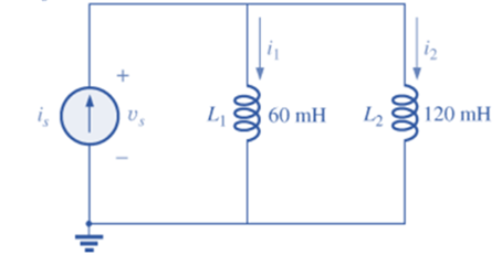
Fig. 14.81
Expert Solution & Answer
Want to see the full answer?
Check out a sample textbook solution
Students have asked these similar questions
4. Find the phasors corresponding to the followinga. ? ? = 21 cos 4? − 15° ?b. ? ? = −8 sin 10? + 70° ?
Given the current i1(t) = 10 sin (20t), the corresponding phasor equivalent I1 is ?
In one measurement of the body's bioelectric impedance, values of Z = 4.09 x 10² and = -6.08° are obtained for the total impedance and the phase angle, respectively. These values assume that the body's resistance R is in series with its capacitance C and that there is no inductance L. Determine the body's (a) resistance and (b) capacitive reactance.
Chapter 14 Solutions
Laboratory Manual for Introductory Circuit Analysis
Ch. 14 - Plot the following waveform versus time showing...Ch. 14 - Repeat Problem 1 for the following sinusoidal...Ch. 14 - What is the derivative of each of the following...Ch. 14 - The voltage across a 20 resistor is as indicated....Ch. 14 - The current through a 6.8 k ) resistor is as...Ch. 14 - Determine the inductive reactance (in ohms) of a 2...Ch. 14 - Determine the closest standard value inductance...Ch. 14 - Determine the frequency at which a 47 mH...Ch. 14 - The current through a 20 inductive reactance is...Ch. 14 - The current through a 0.1 H coil is given. What is...
Ch. 14 - The voltage across a 40 inductive reactance is...Ch. 14 - The voltage across a 0.2 H coil is given. What is...Ch. 14 - Determine the capacitive reactance (in ohms) of a...Ch. 14 - Determine the closest standard value capacitance...Ch. 14 - Determine the frequency at which a 3.9 F capacitor...Ch. 14 - The voltage across a 2.5 capacitive reactance is...Ch. 14 - The voltage across a 1 F capacitor is given. What...Ch. 14 - The current through a 2 k capacitive reactance is...Ch. 14 - The current through a 0.56 F capacitor is given....Ch. 14 - For the following pairs of voltages and currents,...Ch. 14 - Repeat Problem 20 for the following pairs of...Ch. 14 - Plot XL versus frequency for a 3 mH coil using a...Ch. 14 - Plot XC versus frequency for a 1 F capacitor using...Ch. 14 - At what frequency will the reactance of a 1 F...Ch. 14 - The reactance of a coil equals the resistance of a...Ch. 14 - Determine the frequency at which a 1 F capacitor...Ch. 14 - Determine the capacitance required to establish a...Ch. 14 - Find the average power loss and power factor for...Ch. 14 - If the current through and voltage across an...Ch. 14 - A circuit dissipates 100 W (average power) at 150...Ch. 14 - The power factor of a circuit is 0.5 lagging. The...Ch. 14 - In Fig.14.77, e=120sin(260t+20). a. What is the...Ch. 14 - In Fig. 14.78, e=220sin(1000t+60). a. Find the...Ch. 14 - In Fig. 14.79, i=30103sin(2500t20). a. Find the...Ch. 14 - For the network in Fig. 14.80 and the applied...Ch. 14 - For the network in Fig. 14.81 and the applied...Ch. 14 - Convert the following from rectangular to polar...Ch. 14 - Convert the following from rectangular to polar...Ch. 14 - Convert the following from polar to rectangular...Ch. 14 - Convert the following from polar to rectangular...Ch. 14 - Perform the following additions in rectangular...Ch. 14 - Perform the following subtractions in rectangular...Ch. 14 - Perform the following operations with polar...Ch. 14 - Perform the following multiplications in...Ch. 14 - Perform the following multiplications in polar...Ch. 14 - Perform the following divisions in polar form:...Ch. 14 - Perform the following divisions, and leave the...Ch. 14 - Perform the following operations, and express your...Ch. 14 - Prob. 49PCh. 14 - Determine a solution for x and y if...Ch. 14 - Determine a solution for x and y if...Ch. 14 - Express the following in phasor from:...Ch. 14 - Express the following in phasor form:...Ch. 14 - Express the following phasor currents and voltages...Ch. 14 - For the system in Fig. 14.82, find the sinusoidal...Ch. 14 - For the system in Fig. 14.83 find the sinusoidal...Ch. 14 - Find the sinusoidal expression for the voltage Ua...Ch. 14 - Find the sinusoidal expression for the current i1...Ch. 14 - Plot icandUc versus time for the network in Fig....Ch. 14 - Plot the magnitude and phase angle of the current...Ch. 14 - Plot the total impedance of the configuration in...
Knowledge Booster


Learn more about
Need a deep-dive on the concept behind this application? Look no further. Learn more about this topic, electrical-engineering and related others by exploring similar questions and additional content below.Similar questions
- Which component of impedance is not dependent on the frequency of the source of voltage? A. capacitance reactance B. inductive reactance C. resistance D. all are independent of the frequency of the sourcearrow_forwardWhat impedance vector (0- j15) Ohms represents:A. A pure resistance. C. A pure capacitance.B. A pure inductance. D. An inductance combined with a capacitance.arrow_forwardFind total impedance, Reactive power, capacitane, power factor and resistive current Given: Apparent Power: 1878.12 VA, Angle Theta 58.06 degrees, Capacitive reactance 200Ωarrow_forward
- determine the inductive reactance of rlc series ac circuit given the ff: rms current=7.5A voltage=5V resistance=150ohms capacitive resitance=160ohm source average power=2.5Warrow_forwardThe voltage v(t) across the terminal a and b is a sinusoidal voltage having a frequency w = 100 radians/s. When the inductor current i(t) is in phase with the voltage v(t), the magnitude of the impedance Z (in ohm) seen between the terminals a and b is...arrow_forwardIf the phasor voltage across an element is given by V=100∠120∘ and the phasor current through the same element is given by I=50∠30∘, which of the following basic circuit elements best represents this element? a. Insufficient information is given. b. Capacitor c. Some combination of these basic elements d. Resistor e. Inductorarrow_forward
- The voltage applied to a purely inductive coil of self-inductance 15.9 mH is given by the equation v = 100 sin 314t + 75 sin 942t + 50 sm 1570t . Find the equation of the resulting current wave.arrow_forwardA resistor'R' with resistance value of 24 ohm, an inductor 'L' with inductance 20mH, and a capacitor 'C' with capacitance 50 micro Farrad are connected in series with a AC voltage v(t) where v(t) = 50 cos (2 vt + 30 degrees) v. Determine the current i(t) and total impedance if the frequency f is i. 60 Hz ii. 400Hzarrow_forwardUsing the phase shift of 72º from the Experiment, determine the inductance value, L, of the inductor shown. Vr(t) =3.7272 cos(4000 t - 72°) [V]arrow_forward
- The resistance and inductance of a coil can be obtained by connecting the coil in series with a known resistance R and measuring the coil voltage Vcoil, the resistor voltage Vr and the total voltage V. The frequency must also be known, but the phase angles of the voltages are not known. Given that f = 60 Hz, R = 10 ohms, Vcoil = 22.4 V, Vr = 20 V and V = 36V. Calculate Xl and Xcarrow_forwardThe power factor angle of a purely inductive circuit is 0 degrees Select one: True Falsearrow_forwardImpedance of AC circuit and Admittance of AC circuitSHOW THE CIRCUIT USING ANY SOFTWARE OR YOU CAN DRAW IT MANUAALYY thNAKSSarrow_forward
arrow_back_ios
SEE MORE QUESTIONS
arrow_forward_ios
Recommended textbooks for you
 Introductory Circuit Analysis (13th Edition)Electrical EngineeringISBN:9780133923605Author:Robert L. BoylestadPublisher:PEARSON
 Delmar's Standard Textbook Of ElectricityElectrical EngineeringISBN:9781337900348Author:Stephen L. HermanPublisher:Cengage Learning
 Programmable Logic ControllersElectrical EngineeringISBN:9780073373843Author:Frank D. PetruzellaPublisher:McGraw-Hill Education
 Fundamentals of Electric CircuitsElectrical EngineeringISBN:9780078028229Author:Charles K Alexander, Matthew SadikuPublisher:McGraw-Hill Education
 Electric Circuits. (11th Edition)Electrical EngineeringISBN:9780134746968Author:James W. Nilsson, Susan RiedelPublisher:PEARSON
 Engineering ElectromagneticsElectrical EngineeringISBN:9780078028151Author:Hayt, William H. (william Hart), Jr, BUCK, John A.Publisher:Mcgraw-hill Education,
Introductory Circuit Analysis (13th Edition)
Electrical Engineering
ISBN:9780133923605
Author:Robert L. Boylestad
Publisher:PEARSON
Delmar's Standard Textbook Of Electricity
Electrical Engineering
ISBN:9781337900348
Author:Stephen L. Herman
Publisher:Cengage Learning
Programmable Logic Controllers
Electrical Engineering
ISBN:9780073373843
Author:Frank D. Petruzella
Publisher:McGraw-Hill Education
Fundamentals of Electric Circuits
Electrical Engineering
ISBN:9780078028229
Author:Charles K Alexander, Matthew Sadiku
Publisher:McGraw-Hill Education
Electric Circuits. (11th Edition)
Electrical Engineering
ISBN:9780134746968
Author:James W. Nilsson, Susan Riedel
Publisher:PEARSON
Engineering Electromagnetics
Electrical Engineering
ISBN:9780078028151
Author:Hayt, William H. (william Hart), Jr, BUCK, John A.
Publisher:Mcgraw-hill Education,
02 - Sinusoidal AC Voltage Sources in Circuits, Part 1; Author: Math and Science;https://www.youtube.com/watch?v=8zMiIHVMfaw;License: Standard Youtube License