
Loose Leaf for Engineering Circuit Analysis Format: Loose-leaf
9th Edition
ISBN: 9781259989452
Author: Hayt
Publisher: Mcgraw Hill Publishers
expand_more
expand_more
format_list_bulleted
Videos
Textbook Question
Chapter 14, Problem 72E
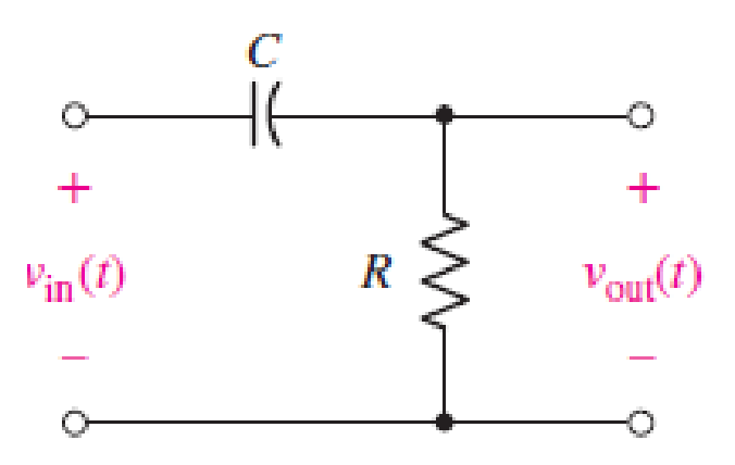
For the network represented schematically in Fig. 14.65, (a) write the transfer function H(s) ≡ Vout(s)/Vin(s); (b) determine the poles and zeros of H(s).
Expert Solution & Answer
Want to see the full answer?
Check out a sample textbook solution
Students have asked these similar questions
Examine the closed loop stability of a system whose open-loop transfer function is given by.G(s) H(s) =1+4s/s^2(1+s )(1+2s) use nyquist plot
Measurements conducted on a servomechanism show the system response to be:
C (t) = 0.3 e 60t + 1.5 e 10t, when subjected to a unit step input.
[1].Obtain the expression for the closed-loop transfer function. [2].Determine the undamped natural frequency and damping ratio of the system.
a) Subtract the system's transfer function (H (S) = Y (S) / R (S)).
b) Using the Routh criterion, the limit value of K coefficient for the system to be stable. Find.
Chapter 14 Solutions
Loose Leaf for Engineering Circuit Analysis Format: Loose-leaf
Ch. 14.1 - Identify all the complex frequencies present in...Ch. 14.1 - Use real constants A, B, C, , and so forth, to...Ch. 14.2 - Let f (t) = 6e2t [u(t + 3) u(t 2)]. Find the (a)...Ch. 14.3 - Prob. 4PCh. 14.3 - Prob. 5PCh. 14.4 - Prob. 6PCh. 14.4 - Prob. 7PCh. 14.4 - Prob. 8PCh. 14.4 - Prob. 9PCh. 14.5 - Prob. 10P
Ch. 14.5 - Prob. 11PCh. 14.5 - Prob. 12PCh. 14.6 - Prob. 13PCh. 14.7 - Prob. 14PCh. 14.7 - Prob. 15PCh. 14.8 - Find the mesh currents i1 and i2 in the circuit of...Ch. 14.8 - Prob. 17PCh. 14.8 - Prob. 18PCh. 14.9 - Using the method of source transformation, reduce...Ch. 14.9 - Prob. 20PCh. 14.10 - The parallel combination of 0.25 mH and 5 is in...Ch. 14.11 - Prob. 22PCh. 14.11 - Prob. 23PCh. 14.11 - Prob. 24PCh. 14.11 - Prob. 25PCh. 14.12 - Prob. 26PCh. 14 - Determine the conjugate of each of the following:...Ch. 14 - Compute the complex conjugate of each of the...Ch. 14 - Several real voltages are written down on a piece...Ch. 14 - State the complex frequency or frequencies...Ch. 14 - For each of the following functions, determine the...Ch. 14 - Use real constants A, B, , , etc. to construct the...Ch. 14 - The following voltage sources AeBt cos(Ct + ) are...Ch. 14 - Prob. 8ECh. 14 - Compute the real part of each of the following...Ch. 14 - Your new assistant has measured the signal coming...Ch. 14 - Prob. 11ECh. 14 - Prob. 12ECh. 14 - Prob. 13ECh. 14 - Prob. 14ECh. 14 - Prob. 15ECh. 14 - Prob. 16ECh. 14 - Determine F(s) if f (t) is equal to (a) 3u(t 2);...Ch. 14 - Prob. 18ECh. 14 - Prob. 19ECh. 14 - Prob. 20ECh. 14 - Prob. 21ECh. 14 - Evaluate the following: (a)[(2t)]2 at t = 1;...Ch. 14 - Evaluate the following expressions at t = 0: (a)...Ch. 14 - Prob. 24ECh. 14 - Prob. 25ECh. 14 - Prob. 26ECh. 14 - Prob. 27ECh. 14 - Prob. 28ECh. 14 - Prob. 29ECh. 14 - Prob. 30ECh. 14 - Prob. 31ECh. 14 - Prob. 32ECh. 14 - Prob. 33ECh. 14 - Obtain the time-domain expression which...Ch. 14 - Prob. 35ECh. 14 - Prob. 36ECh. 14 - Prob. 37ECh. 14 - Prob. 38ECh. 14 - Prob. 39ECh. 14 - Prob. 40ECh. 14 - Prob. 41ECh. 14 - Obtain, through purely legitimate means, an...Ch. 14 - Prob. 43ECh. 14 - Employ the initial-value theorem to determine the...Ch. 14 - Prob. 45ECh. 14 - Prob. 46ECh. 14 - Prob. 47ECh. 14 - Prob. 48ECh. 14 - Prob. 49ECh. 14 - Prob. 52ECh. 14 - Determine v(t) for t 0 for the circuit shown in...Ch. 14 - Prob. 54ECh. 14 - Prob. 55ECh. 14 - For the circuit of Fig. 14.54, (a) draw both...Ch. 14 - Prob. 58ECh. 14 - Prob. 59ECh. 14 - Prob. 60ECh. 14 - For the circuit shown in Fig. 14.58, let is1 =...Ch. 14 - Prob. 63ECh. 14 - Prob. 64ECh. 14 - For the circuit shown in Fig. 14.62, determine the...Ch. 14 - Prob. 67ECh. 14 - Prob. 68ECh. 14 - Determine the poles and zeros of the following...Ch. 14 - Use appropriate means to ascertain the poles and...Ch. 14 - Prob. 71ECh. 14 - For the network represented schematically in Fig....Ch. 14 - Prob. 73ECh. 14 - Prob. 74ECh. 14 - Prob. 75ECh. 14 - Prob. 76ECh. 14 - Prob. 77ECh. 14 - Prob. 78ECh. 14 - Prob. 79ECh. 14 - Prob. 80ECh. 14 - Prob. 81ECh. 14 - Prob. 82ECh. 14 - Design a circuit which produces the transfer...Ch. 14 - Prob. 84ECh. 14 - Prob. 85ECh. 14 - An easy way to get somebodys attention is to use a...Ch. 14 - Prob. 87E
Knowledge Booster


Learn more about
Need a deep-dive on the concept behind this application? Look no further. Learn more about this topic, electrical-engineering and related others by exploring similar questions and additional content below.Similar questions
- R = 0.5 C = 0.5 Let the transfer function a driver be denoted as ,arrow_forwardThe Signal Flow Graph For A System given. Find the transfer function. Y(s)/U(s)arrow_forward1.Draw the s-domain equivalent circuit for the circuit shown in Figure Q1.2 and then find the norton equivalent of the respective circuit you have drawn (with respect to terminal A-B)2.With the help of the Norton equivalent circuit in previous answer, calculate the transfer function for the circuit shown in Figure Q1.2.arrow_forward
- In the system given with the transfer function G(s)=10/(s+10), when the input value is a unit step,Calculate the time constant Tc, the rise time Tr, and the setting time Ts.arrow_forwardObtain the transfer function Y1(s)/F(s) for this system.arrow_forwardUse the signal flow graph method for finding the transfer function Y(S)/R(S)arrow_forward
- Determine the a) transfer function, b) system zeros, and c) system poles of the given electrical network if theinput is the source voltage, Vi(s), and the output is the voltage across the 0.6 H inductor.arrow_forwardFor the network shown below, determine the transfer function G(s) = Vo(s)/Vi(s). show the details of your work. Write your answer on a white typewriting paper, scan it in JPEG format, and paste it into the space provided below.arrow_forwardDetermine whether the system defined by the following transfer functions are stable or not. Use Continued Method.arrow_forward
- The transfer function of the system whose blog diagram is given below (H (S) = Y (S) / R (S)) remove.arrow_forwardAn input, r(t), defined asr(t) = 0, t < 0r(t) 3.0 t >0is applied to a system that can be described by a transfer function, T(p), whereT(p) = (24p + 208)/(p2+12p+52)Determine the system response, y(t), and sketch the output waveform.arrow_forwardThe transfer function of a plant is given in the image. Design a leading compensator per root locus to bring the closed-loop poles to belocated at s = - 2 ± j3.46.arrow_forward
arrow_back_ios
SEE MORE QUESTIONS
arrow_forward_ios
Recommended textbooks for you
 Introductory Circuit Analysis (13th Edition)Electrical EngineeringISBN:9780133923605Author:Robert L. BoylestadPublisher:PEARSON
 Delmar's Standard Textbook Of ElectricityElectrical EngineeringISBN:9781337900348Author:Stephen L. HermanPublisher:Cengage Learning
 Programmable Logic ControllersElectrical EngineeringISBN:9780073373843Author:Frank D. PetruzellaPublisher:McGraw-Hill Education
 Fundamentals of Electric CircuitsElectrical EngineeringISBN:9780078028229Author:Charles K Alexander, Matthew SadikuPublisher:McGraw-Hill Education
 Electric Circuits. (11th Edition)Electrical EngineeringISBN:9780134746968Author:James W. Nilsson, Susan RiedelPublisher:PEARSON
 Engineering ElectromagneticsElectrical EngineeringISBN:9780078028151Author:Hayt, William H. (william Hart), Jr, BUCK, John A.Publisher:Mcgraw-hill Education,
Introductory Circuit Analysis (13th Edition)
Electrical Engineering
ISBN:9780133923605
Author:Robert L. Boylestad
Publisher:PEARSON
Delmar's Standard Textbook Of Electricity
Electrical Engineering
ISBN:9781337900348
Author:Stephen L. Herman
Publisher:Cengage Learning
Programmable Logic Controllers
Electrical Engineering
ISBN:9780073373843
Author:Frank D. Petruzella
Publisher:McGraw-Hill Education
Fundamentals of Electric Circuits
Electrical Engineering
ISBN:9780078028229
Author:Charles K Alexander, Matthew Sadiku
Publisher:McGraw-Hill Education
Electric Circuits. (11th Edition)
Electrical Engineering
ISBN:9780134746968
Author:James W. Nilsson, Susan Riedel
Publisher:PEARSON
Engineering Electromagnetics
Electrical Engineering
ISBN:9780078028151
Author:Hayt, William H. (william Hart), Jr, BUCK, John A.
Publisher:Mcgraw-hill Education,
Nyquist 1 - what is a Nyquist diagram?; Author: John Rossiter;https://www.youtube.com/watch?v=mgIvOk9JGKY;License: Standard Youtube License