
Videos
(a)
Design a circuit which produces a transfer function of
(a)
Explanation of Solution
Problem design:
Synthesize a circuit that will yield the transfer function
Calculation:
The transfer function of the circuit is,
The above equation is written as,
For the above transfer function, it has two repeated zeros at
The Figure 14.39 (b) in the textbook, that shows a cascade two stages of the circuit with a zero at
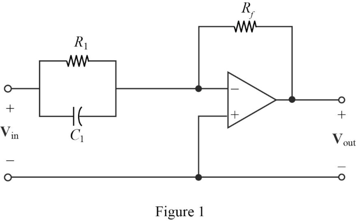
For a single zero,
Substitute
Let arbitrarily consider
Substitute
Transfer function:
The input impedance of the cascaded circuit is,
Then, write the Formula for the transfer function for the cascaded two stage amplifier.
Substitute
Thus, consider that the transfer function for
Substitute 1 for
Completing the design by letting
Since, two repeated zeros at
Therefore,
Substitute
Thus, the final design of the circuit is,
Conclusion:
Thus, a circuit is designed which produces a transfer function of
(b)
Design a circuit which produces a transfer function of
(b)
Explanation of Solution
Problem design:
Synthesize a circuit that will yield the transfer function
Calculation:
The transfer function of the circuit is,
Consider the transfer function for the cascaded circuit as below.
The above transfer function, it has two poles at
The Figure 14.39 (a) in the textbook, that shows a cascade two stages of the circuit with pole at
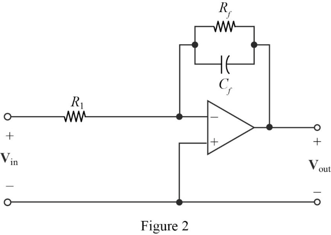
The above Figure 2, is the representation for the first stage and second stage of a cascaded circuit to be drawn.
Consider the denominator of given transfer function and the first pole as
Where,
Substitute
Let arbitrarily consider
Substitute
Transfer function:
Find the feedback impedance of the cascaded circuit in Figure 2.
Write the formula for the transfer function of the cascaded circuit in Figure 2 as follows
Substitute
Therefore, consider the transfer function for the first pole
Substitute 500 for
Completing the design by letting
Consider the denominator of given transfer function and the first pole as
Where,
Substitute
Arbitrarily consider
Substitute
Therefore, consider the transfer function for the second pole
Substitute 100 for
Completing the design by letting
Then, from the transfer function of the two stages write the complete transfer function as follows.
Substitute
Thus, the final design of the circuit is,
Conclusion:
Thus, a circuit is designed which produces a transfer function of
Want to see more full solutions like this?
Chapter 14 Solutions
Loose Leaf for Engineering Circuit Analysis Format: Loose-leaf


- The Signal Flow Graph For A System given. Find the transfer function. Y(s)/U(s)arrow_forwardR = 0.5 C = 0.5 Let the transfer function a driver be denoted as ,arrow_forwardA system is described by the differential equation (see attached). a)What is the order of the system. How many poles does the system's transfer function have. How many states are needed to describe the system completely.b) Determine the system's transfer function, Y(s)/U(s) (the poles of the system are at ―1, ― 2, and ―4);c) Determine matrices A, B, C, and D to describe the system in state-space form x' = Ax + Bu, y = Cx + Du.arrow_forward
- Given the system, give the difference equation and the impulse response of the system, y(-1) = 2 y(-2)=1arrow_forwardThe transfer function of a system is given in the image. (j is the imaginary part) Determine: (a) The impulse response. (b) Whether the system is stable. (c) The differential equation that represents the system.arrow_forwardA state space representation for the transfer function given below, The value of C will be * [6 1] [5 6] [6 5] [1 6]arrow_forward
- 1. Derive the transfer function, G(s) of the system using V(s) as the input and Vc(s) as the output. See electrical circuit attached.arrow_forwardThe transfer function of a system is given by H(s) = 1/[s^2(s − 2)]. Find out the impulse response of the system if u(t) is used to denote the unit-step signal.arrow_forward(Signals and Systems) Determine whether the systems with these transfer functions are stable, marginally stable or unstable by determining the poles.arrow_forward
- x(t)=cos(2*\pi *15t) a signal defined in the form of a signal is introduced into a system whose transfer function is given below. In this case, what is the signal obtained at the output.arrow_forward4. Find the Transfer Function of the given circuit. (Kindly provide a CLEAR and COMPLETE solution also the answer should be TYPEWRITTEN)arrow_forwarddetermine the transfer function z(s)/u(s) for the differential equation that will be attachedarrow_forward
 Introductory Circuit Analysis (13th Edition)Electrical EngineeringISBN:9780133923605Author:Robert L. BoylestadPublisher:PEARSON
 Delmar's Standard Textbook Of ElectricityElectrical EngineeringISBN:9781337900348Author:Stephen L. HermanPublisher:Cengage Learning
 Programmable Logic ControllersElectrical EngineeringISBN:9780073373843Author:Frank D. PetruzellaPublisher:McGraw-Hill Education
 Fundamentals of Electric CircuitsElectrical EngineeringISBN:9780078028229Author:Charles K Alexander, Matthew SadikuPublisher:McGraw-Hill Education
 Electric Circuits. (11th Edition)Electrical EngineeringISBN:9780134746968Author:James W. Nilsson, Susan RiedelPublisher:PEARSON
 Engineering ElectromagneticsElectrical EngineeringISBN:9780078028151Author:Hayt, William H. (william Hart), Jr, BUCK, John A.Publisher:Mcgraw-hill Education,