
Videos
Design a circuit which produces the transfer function
Design a circuit which produces a transfer function of
Explanation of Solution
Given data:
The given transfer function is,
Calculation:
The transfer function of the circuit is,
Equation (1) is written as,
For numerator:
From equation (2), for the numerator
The Figure 14.39 (b) in the textbook, that shows a cascade two stages of the circuit with a zero at
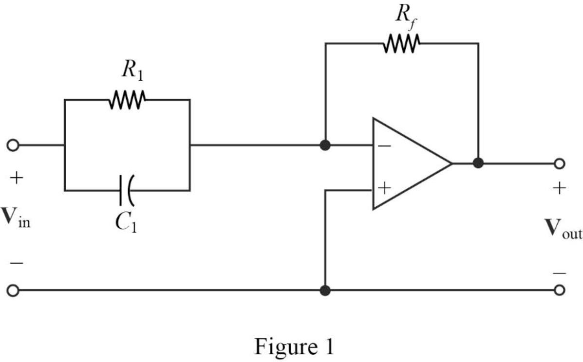
From the Figure 1, a single zero can be written as,
Substitute
Consider the value of
Substitute
Transfer function:
The input impedance of the cascaded circuit in Figure 1 is,
Then, write the Formula for the transfer function for the cascaded two stage amplifier.
Substitute
Thus, consider that the transfer function for
Substitute 50 for
Completing the design by letting
Thus, the final design of the circuit is,
For denominator:
From the transfer function shown in equation (2), it has two repeated poles at
The Figure 14.39 (a) in the textbook, that shows a cascade two stages of the circuit with pole at
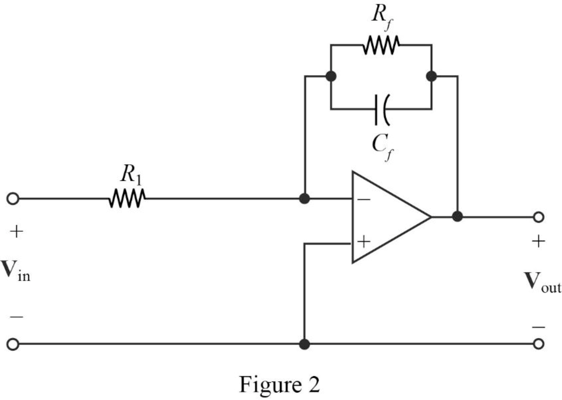
Consider that the cascaded circuit for the two poles representation as shown in Figure 2.
From Figure 2, and the denominator of given transfer function a first pole at
Where, the circuit parameters are considered as
Substitute
Let arbitrarily consider
Substitute 13.3 for
Transfer Function:
Find the feedback impedance of the cascaded circuit in Figure 2.
Write the formula for the transfer function of the cascaded circuit in Figure 2 as follows
Substitute
Therefore, consider the transfer function
Substitute 75 for
Completing the design by letting
Since, two repeated poles are at same
Therefore, the complete transfer function for the denominator part is,
Substitute
Thus, the final design of the two stages cascaded circuit for the denominator part is,
Thus, the overall transfer function of the complete circuit using the transfer function of numerator
Substitute
The input will be inverted, and adding an inverting amplifier with gain of 1 to provide the transfer function as follows.
Conclusion:
Thus, a circuit is designed which produces a transfer function of
Want to see more full solutions like this?
Chapter 14 Solutions
Engineering Circuit Analysis
Additional Engineering Textbook Solutions
Fundamentals of Electric Circuits
Electric Circuits. (11th Edition)
Principles Of Electric Circuits
Electronics Fundamentals: Circuits, Devices & Applications
ELECTRICITY FOR TRADES (LOOSELEAF)
Fundamentals of Applied Electromagnetics (7th Edition)


- Open-loop transfer function of a system is 10 G( s(5s+1) input signal is x{t)=1(t) , Find steady-state error of the system.arrow_forwardFor the following transfer function, write the corresponding differential equations:arrow_forwardObtain the overall Transfer Function of the following systems. Please show each system's step-by-step block diagram solution.arrow_forward
- The circuit is driven by a voltage source whosevoltage increases linearly with time, namely, vg=50tu(t) V. Use the transfer function to find vo.arrow_forwardFind the expression for the signal i0(t) of the circuit below, knowing that the input is a voltage signal Vin(t) = 60 u(t) V and that the capacitor is initially charged with a voltage v of 1 V and the inductor with a current i of 0.5 A. Find the transfer function H(s) = i0(t)/Vin(t).arrow_forwardDetermine the following. 1. Natural frequency 2. Damping ratio for the closed loop transfer function of a system is as follows; Units not necessary 25/s^2+4s+50arrow_forward
- A system has a closed-loop transfer function T(s) = 1/s^3 + 5s^2 + 20s + 6 (a)Determine whether the system is stable.(b)Determine the roots of the characteristic equation.(c)Plot the response of the system to a unit step input.arrow_forwardThe Signal Flow Graph For A System given. Find the transfer function. Y(s)/U(s)arrow_forwardFor each of the circuits shown below, obtain the transfer function H(s) = Vo(s)/Vi(s) and its corresponding impulse response h(t). Sketch the root locus diagram:arrow_forward
- Which of the following is the H (s) transfer function of the system whose block diagram is given? s / (4s + 3)4 s / (3s + 1)4 s / (3s + 2)s / (s + 4)4 s / (s + 1)3 s / (s + 4)arrow_forwardRoot Locus Question Utilizing root locus techniques (by hand) prove that for the transfer function K*G(s) where G(s) = 1/(s^2+s+10) there is no value for K that will allow for less than 16% overshoot. Sketch the region of allowance on the root locus which would give less than 16% overshoot as added proof to the statement 5arrow_forwardA circuit with a resistor and capacitor in series is subjected to a number of different input voltages as shown in attached image: 1. Derive the transfer function, G(s) of the system using v(s) as the input and vc(s) as the output.arrow_forward
 Introductory Circuit Analysis (13th Edition)Electrical EngineeringISBN:9780133923605Author:Robert L. BoylestadPublisher:PEARSON
 Delmar's Standard Textbook Of ElectricityElectrical EngineeringISBN:9781337900348Author:Stephen L. HermanPublisher:Cengage Learning
 Programmable Logic ControllersElectrical EngineeringISBN:9780073373843Author:Frank D. PetruzellaPublisher:McGraw-Hill Education
 Fundamentals of Electric CircuitsElectrical EngineeringISBN:9780078028229Author:Charles K Alexander, Matthew SadikuPublisher:McGraw-Hill Education
 Electric Circuits. (11th Edition)Electrical EngineeringISBN:9780134746968Author:James W. Nilsson, Susan RiedelPublisher:PEARSON
 Engineering ElectromagneticsElectrical EngineeringISBN:9780078028151Author:Hayt, William H. (william Hart), Jr, BUCK, John A.Publisher:Mcgraw-hill Education,