
Concept explainers
Videos
(a)
The value of
(a)
Answer to Problem 63E
The voltage
Explanation of Solution
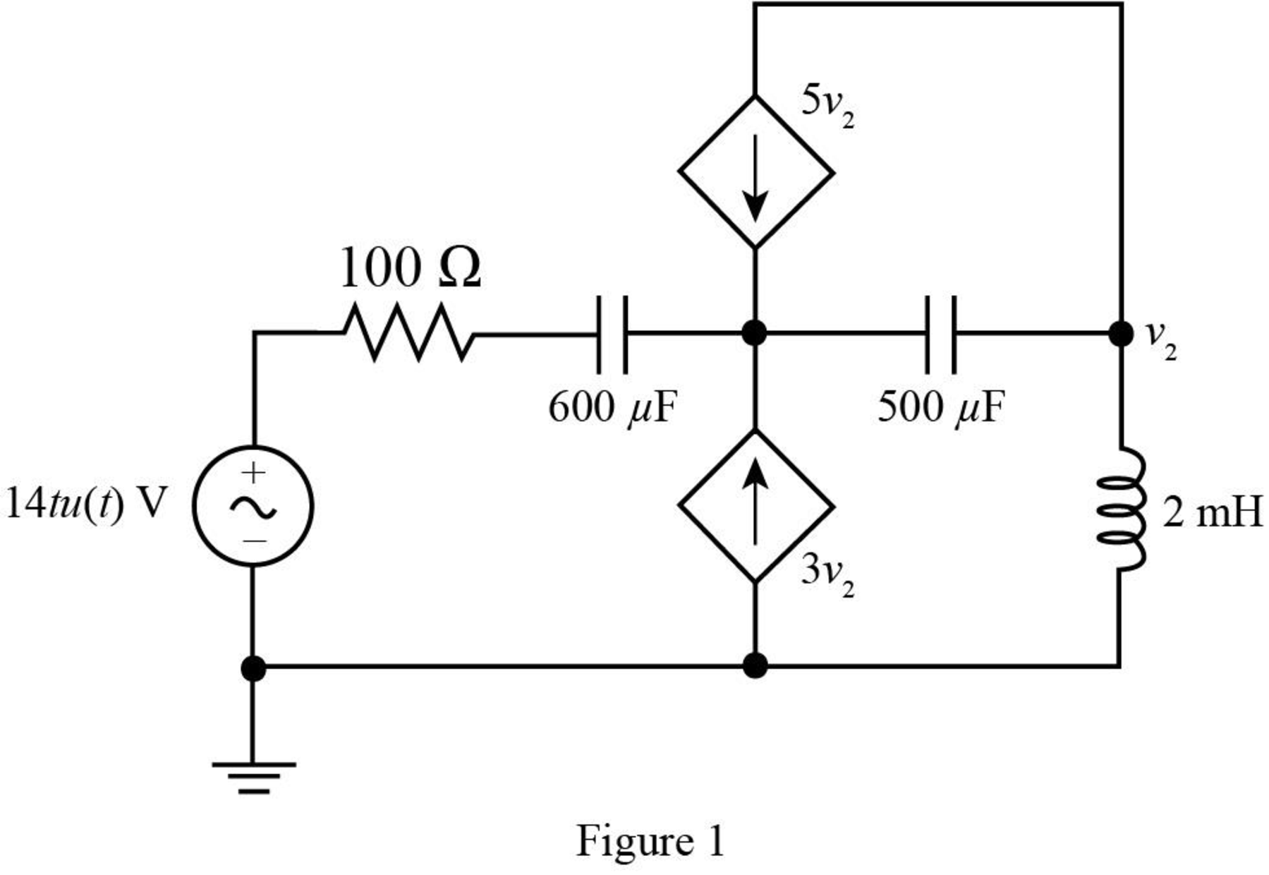
Given data:
The resistive component of the circuit is of
The capacitive components of the circuit are
The values of voltage dependent current sources are
The inductive component of the circuit is of
The input voltage of the circuit is
The time
The given diagram is shown in Figure 1.
Calculation:
Let the resistance
The conversion of
The conversion of
The conversion of
The conversion from
The conversion from
The voltage source
The Laplace transform of capacitance is given by,
The Laplace transform of
The Laplace transform of
The Laplace transform of inductor is given by,
The Laplace transform of
Mark the nodes apply mesh analysis to the circuit and redraw the circuit in
The required diagram is shown in Figure 2.
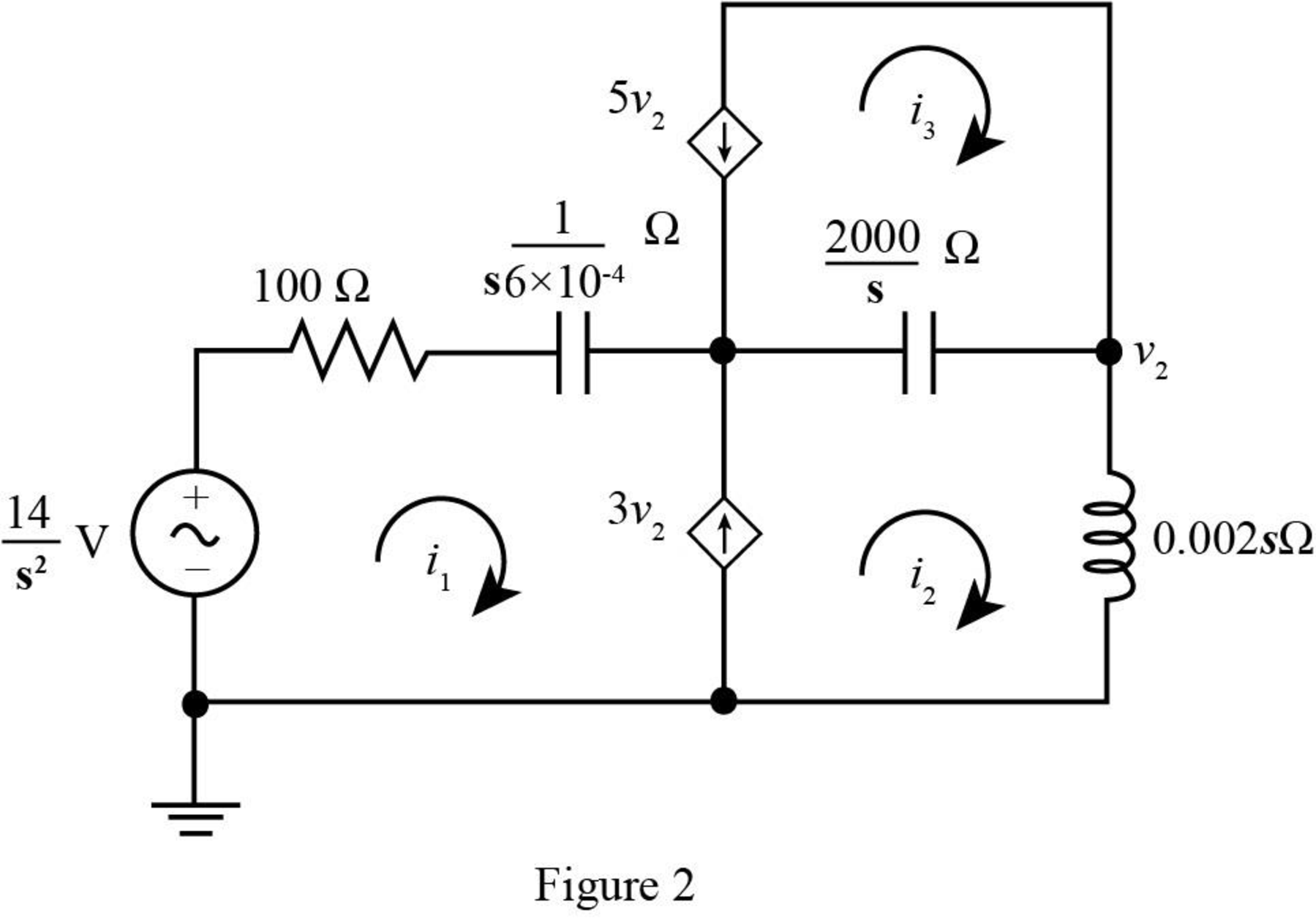
The output voltage
The value of node voltage
The current source
The super mesh equation is given as,
Substitute
The current flowing through the loop 3 is given by,
Substitute
Apply Kirchhoff’s voltage law at the super mesh.
Substitute
Solve further as,
Substitute
The above equation in partial form is written as,
Substitute
Substitute
Substitute
Substitute
Apply inverse Laplace transform to the above equation.
7
The conversion from
The conversion of
Substitute
Conclusion:
Therefore he value of
(b)
The value of
(b)
Answer to Problem 63E
The voltage
Explanation of Solution
Given data:
The value of
Calculation:
The conversion from
The conversion of
Substitute
Conclusion:
Thus, the voltage
(c)
The value of
(c)
Answer to Problem 63E
The voltage
Explanation of Solution
Given data:
The value of
Calculation:
Substitute
Conclusion:
Thus, the voltage
Want to see more full solutions like this?
Chapter 14 Solutions
Engineering Circuit Analysis


- Find the root of the equation. S^2+2S+5arrow_forwardAn 2 kΩ resistor, a 6.25 H inductor, and a 250 nF capacitor are inparallel. Express the s-domain impedance of this parallel combination asa rational function.arrow_forwardGraph the following functions for the given x[n]= {…,0,2,-2,0,1,3,-2,-3,1,-1,0,…} signal. a) y[n]=x[n](u[n+3]-u[n-2])-2∂[n]+3∂[n-3]x[n b) y[n]=2x[-n]+(x[n])²+x[-n+2]arrow_forward
- The mathematical models of some continuous time systems are given above. x(t) is the input signal of the system, and y(t) is the output signal of the system. Which of the following systems is linear and which is nonlinear?arrow_forwardWhen the unit step function is applied to the system input whose block diagram is given below, the output response takes the value c (0.2) = 0.11 fort = 0.2 s and c (infinity) = 0.333 for t = infinity. What is the time constant of the system? calculate.arrow_forwardMake the equation s(s+1)(s+2)+K=0 in the form of 1+KF(s) and explain the drawing of root-locus curves. (Note: Indicate the splitting points, centers and angles of the asymptotes)arrow_forward
- 40 - When the unit step function is applied to the system input given the block diagram below, the output response takes the value c (infinity) = 3 for t = infinity. So which of the following can be the constants K, a?A) K = 0.05, a = 0.25B) K = 3, a = 1C) K = 0.35, a = 0.55D) K = 1, a = 3E) K = 0.45, a = 0.65arrow_forward1)What is the difference between final value theorem and initial value? 2) When we cant use a final value theorem? Please helparrow_forwardWhen the unit step function is applied to the system input whose block diagram is given below, the output response takes the value c (infinity) = 2 for t = infinity. So which of the following can be the constants K, a?arrow_forward
- The answer of this question on bartleby is of other parts. This is different question. Don't copy that answer. I already have that. I am posting it for the third time. A. Write the state variable equation(s) B. The system equation(s) you obtained in D are (Circle one choice for each statement): Ordinary Differential Equation(s) True False Linear True False Second Order True False Constant Coefficients True Falsearrow_forwardDesign an electrical circuit consists of the following elements, two resistance, two inductance, and one capacitance, obtain the parameters z12, y22, h21, and A.arrow_forwardA)Perform the N=5 point circular convolution of x and h using DFT. B)Perform the N=5 point circular convolution of x and h in time-domain.arrow_forward
 Introductory Circuit Analysis (13th Edition)Electrical EngineeringISBN:9780133923605Author:Robert L. BoylestadPublisher:PEARSON
 Delmar's Standard Textbook Of ElectricityElectrical EngineeringISBN:9781337900348Author:Stephen L. HermanPublisher:Cengage Learning
 Programmable Logic ControllersElectrical EngineeringISBN:9780073373843Author:Frank D. PetruzellaPublisher:McGraw-Hill Education
 Fundamentals of Electric CircuitsElectrical EngineeringISBN:9780078028229Author:Charles K Alexander, Matthew SadikuPublisher:McGraw-Hill Education
 Electric Circuits. (11th Edition)Electrical EngineeringISBN:9780134746968Author:James W. Nilsson, Susan RiedelPublisher:PEARSON
 Engineering ElectromagneticsElectrical EngineeringISBN:9780078028151Author:Hayt, William H. (william Hart), Jr, BUCK, John A.Publisher:Mcgraw-hill Education,