
Videos
How does the voltmeter reading compare to the potential difference across the electrodes? Explain.
If the sliding lead from electrode A were connected at point C along the resistor, would the voltmeter reading be positive, negative, or zero? Explain.
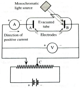
(Hint: Imagine disconnecting the ammeter and evacuated tube from the rest of the circuit, and answering the same question.)
How would you adjust the sliding connection from electrode A in order to make the potential difference across the electrodes
The potential difference reading in the voltmeter.
Voltmeter reading positive, negative or zero.
To adjustment to be made for the Voltmeter reading as positive and negative.
Answer to Problem 1aT
The potential across the electrodes is equal to the potential difference reading in the voltmeter.
Voltmeter reading will be positive.
By reversing the direction of the connection of the variable battery voltmeter can read negative potential.
Explanation of Solution
Introduction:
Photoelectric effect: Electrons from a metal surface are ejected when a light of an appropriate frequency is incident on it.The ejected electrons are called photoelectrons and the whole phenomenon is called photoelectric effect. This effect was explained by The Albert Einstein.
Figure 1 shows the circuit diagram to study the Photoelectric effect (PE).
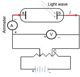
Figure 1: Set up to study photoelectric effect
A monochromatic is incident on one of the electrodes ‘b’ . Electron bonded to a metal requires a minimum energy just to leave the surface of metal is called binding energy of electron, also known as work function of the electron and denoted as
Current is flowing from positive to negative terminal of the battery (shown as red arrows in Figure 1).Therefore, the voltmeter will show the potential across electrode positive as electrons are flowing from high potential to lower potential.
Figure 2 shows the circuit diagram to study the Photoelectric effect (PE). In order to obtain the positive potentialdifference, read by voltmeter, figure 2(1) is applicable, as the electrode ‘b’ exposed to light is connected to negative terminal and other electrode ‘a’to the positive terminal of the battery. To make it more positive, one need to increase the potential of the variable battery that will make the electrode ‘a’more positive, hence will result in more positive potential across the electrodes.
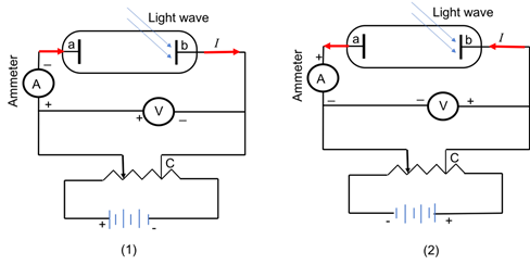
Figure 2: Set up to study photoelectric effect
In order to obtain the negative potential difference,read by voltmeter, figure 2(2) is applicable, as the electrode ‘b’ exposed to light is connected to positive terminal and other electrode ‘a’to the negative terminal of the battery.
Conclusion:
The potential across the electrodes is equal to the potential difference reading in the voltmeter.Voltmeter reading will be positive.By reversing the direction of the connection of the variable battery voltmeter can read negative potential.
Want to see more full solutions like this?
Chapter 14 Solutions
Tutorials in Introductory Physics
Additional Science Textbook Solutions
Conceptual Integrated Science
College Physics
The Cosmic Perspective (8th Edition)
Physics for Scientists and Engineers with Modern Physics
College Physics: A Strategic Approach (4th Edition)
Physics for Scientists and Engineers: A Strategic Approach, Vol. 1 (Chs 1-21) (4th Edition)


- Consider the circuit below (picture attached) How would you add a resistor with a resistance of 7.00 Ω to the circuit so that the current through the 3.0 Ω resistor is maximized? (This is already answered but I believe this correlates with part b. For this part the new resistor must be in parallel with the 4 ohm resistor) By how much does the current through 3.0 Ω resistor increase when you do what was descibed above? (Must be in units of ampheres please.)arrow_forwardYou hook up the circuit shown to the right.a) Write a voltage equation that states how the voltage drops across the bulbs relate to the voltage gain across the battery . Use this equation along with Ohm's law for each bulb to determine the current flowing through the bulbs (& battery).b) Determine the voltage across each bulb.c) In a series circuit with bulbs of different resistances, is a bulb with higher resistance likely to be brighter or dimmer than a bulb with a smaller resistance? Discuss this with your group.d) Calculate the power dissipated by each light bulb.e) Calculate the power provided by the battery. Why was this predictable?f) How does each of the following change if a fourth round bulb is added in series? (you may want to look back over how your answers to (a-c) would change) Current Voltage drop across each bulb Brightness of each bulb g) What happens if one bulb burns out?arrow_forwardHello my dear tutor, Please help me answer this one. Show your solutions or answers. Type only your step by step solutions and answers here, do not handwritten. Failure to follow the above reminders and direction will be marked as not helpful; 3. The series combination of 5.0 F and 20.0 F capacitors is connected in parallel to a 40.0 F capacitor. What is the total charge stored in the combination of capacitors when connected to 100.0 V? A.6500 C B.4400 C C.360 C D.1500 Carrow_forward
- You measured the resistance values and using an ohmmeter directly, and you also determined the values of and from Ohm's law in the two circuit configurations. In addition, the resistance was given from the resistor color-code. Which of these give the most accurate resistance value? Briefly explain your answer. Examine the power use determined for the individual resistors , and the combined resistances for both series and parallel configuration. Based on your observations, write a general equation that describes the "equivalent power" for each configuration. For the series circuit, based on your results, write an equation relating the voltage from the power source to the voltage across each component resistor. For the parallel circuit, based on your results, write an equation relating the current flow from the power source to the currents flow in each component resistor.arrow_forwardConsider the diagram at the right of a parallel circuit. Each light bulb has an identical resistance of R and the battery voltage is V. Use the labeled points on the diagram to answer the following questions. a. If the current at location A is I amperes, then the current at location B is ____ amperes. (Answer in terms of I.) b. If the current at location A is I amperes, then the current at location D is ____ amperes. (Answer in terms of I.) c. If the current at location A is I amperes, then the current at location L is ____ amperes. (Answer in terms of I.) d. If the voltage of the battery is doubled, then the current at location A would be ____ (two times, four times, one-half, one-fourth, etc.) the original value. e. If the voltage of the battery is doubled, then the current at location B would be ____ (two times, four times, one-half, one-fourth, etc.) the original value. f. If the voltage of the battery is doubled, then the current at location D would be ____ (two times, four times,…arrow_forwardIdentical bulbs are shown in the circuit. 1) Is bulb A brighter, dimmer, or the same brightness as bulb B? Explain 2) Is the current through bulb D greater that or less that, or equal to the current through bulb F. Explain. 3) If bulb F is unscrewed from its socket, does bulb B become brighter, dimmer, or stay the same. Explain.arrow_forward
- Consider the circuit shown in (Figure 1). Assume E = 12 V. What is the equivalent capacitance? What is the charge on 3.0 μF capacitor? What is the charge on 4.0 μF capacitor? What is the charge on 6.0 μF capacitor?arrow_forwardGiven the circuit below: If all the currents flowing through R1, R2, and R3 (I1, I2, and I3, respectively) are going in the top junction, what is the equation resulting from applying the Kirchhoff's loop rule for a clockwise loop around the perimeter of the circuit?arrow_forwardPart A3: Set the battery voltage to 12 volts. What resistance is necessary to achieve 2.77 A of current in this circuit? (Get as close as you can.)arrow_forward
- Conceptualize Study figure (a) carefully and make sure you understand how the capacitors are connected.Categorize Figure (a) shows that the circuit contains both series and parallel connections, so we use the rules for series and parallel combinations discussed in this section.Analyze Reduce the combination step by step as indicated in the figure. The c1 = 1.1 µF and 3.0 µF capacitors in figure (a) are in parallel. Find the equivalent capacitance: Ceq = C1 + C2 = 4.1 µF (top red circles) The c2 = 2.0 µF and 6.0 µF capacitors in figure (a) are also in parallel: Ceq = C1 + C2 = 8.0 µF (bottom red circles) The circuit now looks like figure (b). The two capacitors in the upper branch are in series. Find the equivalent capacitance: 1 Ceq = 1 C1 + 1 C2 = 1 4.0µF + 1 4.1µF (top green circles) Ceq = 2.0 µF The two capacitors in the lower branch are also in series. Find the equivalent capacitance: 1…arrow_forwardPart a and b, please. For the circuit shown in the figure (Figure 1) both meters are idealized, the battery has no appreciable internal resistance, and the ammeter reads 1.60 A Part a What does the voltmeter read? Part b What is the emf E of the battery?arrow_forwardFor the structure below, what is the capacitance "between"points A and B, B and C, and A and C. If point A and C are connected with a wire, what is the capacitance between points A and B? For each case, draw the equivalent schematic.arrow_forward
 Glencoe Physics: Principles and Problems, Student...PhysicsISBN:9780078807213Author:Paul W. ZitzewitzPublisher:Glencoe/McGraw-Hill