
MECHANICS OF MATERIALS-TEXT
9th Edition
ISBN: 2810014920922
Author: HIBBELER
Publisher: PEARSON
expand_more
expand_more
format_list_bulleted
Videos
Textbook Question
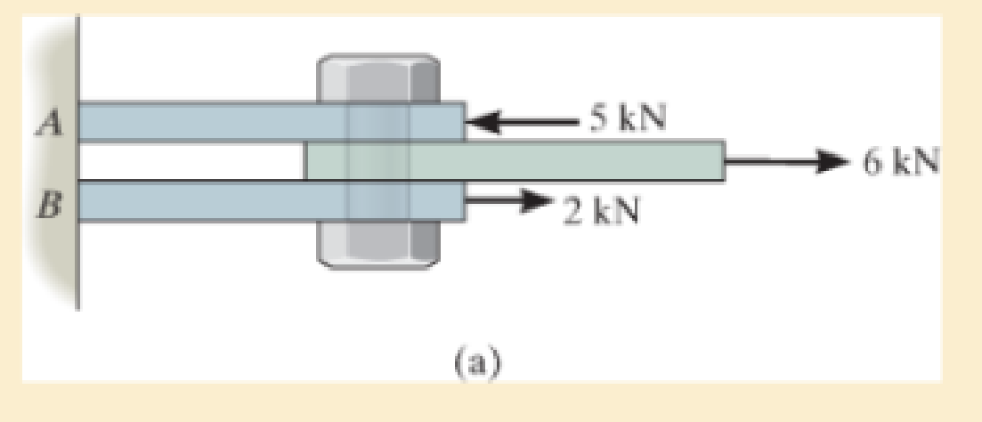
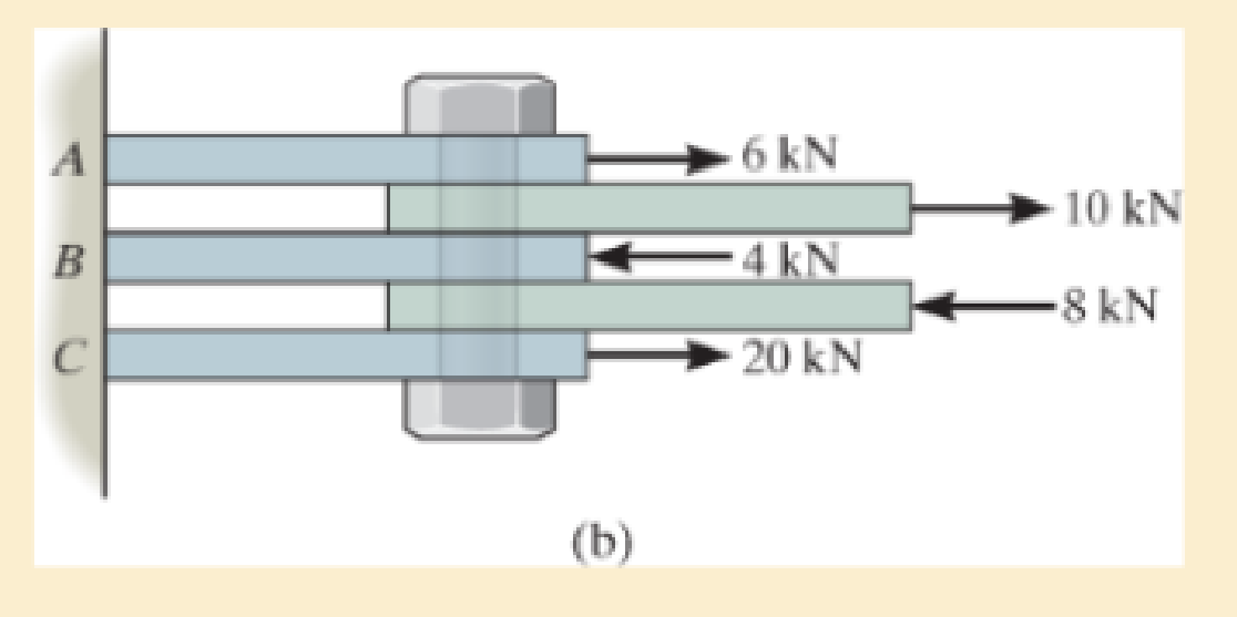
Chapter 1.5, Problem 1.2PP
In each case, determine the largest internal shear force resisted by the bolt. Include all necessary free-body diagrams.
Expert Solution & Answer

Trending nowThis is a popular solution!

Learn your wayIncludes step-by-step video

schedule03:12
Students have asked these similar questions
The bracket is held to the wall using three A-36 steel bolts at B. C, and D. Each bolt has a diameter of 0.8 in. and an unstretched length of 2 in
Part A
2 in
1 in
If a force of P450 lb is placed on the bracket as shown, determine how far, a, the top bracket at bolt D moves away from the wall. For the calculation, assume that the bolts carry no shear; rather, the vertical force of 450 lb is supported by the toe at A. Also, assume that the wall and bracket are rigi
exaggerated deformation of the bolts is shown in the figure
Express your answer to three significent figures and include appropriate units.
?
Value
Units
Submit
Request Answer
Provide Feedback
OMEN Gaming Hub
Application restart required
A software component has b
and OMEN Gaming Hub nee
restarted. Would you like to w
OMEN Gaming Hub now?
RESTART APP
DON'T SHO
Take a "cut" at H (draw a proper FBD) and determine the forces at H.
The bracket is held to the wall using three A-36 steel bolts at B, C, and D. Each bolt has a diameter of 0.5 in. and an unstretched length of 2 in. If a force of 800 lb is placed on the bracket as shown, determine how far, s, the top bracket at bolt D moves away from the wall. For the calculation, assume that the bolts carry no shear; rather, the vertical force of 800 lb is supported by the toe at A. Also, assume that the wall and bracket are rigid. A greatly exaggerated deformation of the bolts is shown.
Chapter 1 Solutions
MECHANICS OF MATERIALS-TEXT
Ch. 1.2 - In each case, explain how to find the resultant...Ch. 1.2 - Determine the resultant internal normal force,...Ch. 1.2 - Determine the resultant internal normal force,...Ch. 1.2 - Determine the resultant internal normal force,...Ch. 1.2 - Determine the resultant internal normal force,...Ch. 1.2 - Determine the resultant internal normal force,...Ch. 1.2 - Determine the resultant internal normal force,...Ch. 1.2 - The shaft is supported by a smooth thrust bearing...Ch. 1.2 - Determine the resultant internal normal and shear...Ch. 1.2 - 1-3. The beam AB is fixed to the wall and has a...
Ch. 1.2 - The shaft is supported by a smooth thrust bearing...Ch. 1.2 - 1-5. Determine the resultant internal loadings in...Ch. 1.2 - 1-6. Determine the normal force, shear force, and...Ch. 1.2 - 1-7. The cable will fail when subjected to a...Ch. 1.2 - *1-8. Determine the resultant internal loadings on...Ch. 1.2 - 1-9. Determine the resultant internal loadings on...Ch. 1.2 - The boom DF of the jib crane and the column DE...Ch. 1.2 - 1-11. The forearm and biceps support the 2-kg load...Ch. 1.2 - *1-12. The serving tray T used on an airplane is...Ch. 1.2 - The blade of the hacksaw is subjected to a...Ch. 1.2 - The blade of the hacksaw is subjected to a...Ch. 1.2 - 1-15. A 150-lb bucket is suspended from a cable on...Ch. 1.2 - *1-16. A 150-lb bucket is suspended from a cable...Ch. 1.2 - 1-17. Determine resultant internal loadings acting...Ch. 1.2 - Prob. 1.18PCh. 1.2 - Prob. 1.19PCh. 1.2 - Prob. 1.20PCh. 1.2 - Prob. 1.21PCh. 1.2 - The metal stud punch is subjected to a force of...Ch. 1.2 - Determine the resultant internal loadings acting...Ch. 1.2 - Prob. 1.24PCh. 1.2 - 1-25. Determine the resultant internal loading...Ch. 1.2 - 1-26. The shaft is supported at its ends by two...Ch. 1.2 - 1-27. The pipe assembly is subjected to a force of...Ch. 1.2 - If the drill bit jams when the brace is subjected...Ch. 1.2 - 1-29. The curved rod AD of radius r has a weight...Ch. 1.2 - A differential element taken from a curved bar is...Ch. 1.5 - In each case, determine the largest internal shear...Ch. 1.5 - Determine the largest internal normal force in the...Ch. 1.5 - Determine the internal normal force at section A...Ch. 1.5 - Prob. 1.5PPCh. 1.5 - The single-V butt joint transmits the force of 5...Ch. 1.5 - The uniform beam is supported by two rods AB and...Ch. 1.5 - Determine the average normal stress on the cross...Ch. 1.5 - Determine the average normal stress on the cross...Ch. 1.5 - If the 600-kN force acts through the centroid of...Ch. 1.5 - Determine the average normal stress at points A,...Ch. 1.5 - Determine the average normal stress in rod AB if...Ch. 1.5 - The supporting wheel on a scaffold is held in...Ch. 1.5 - Prob. 1.32PCh. 1.5 - The bar has a cross-sectional area A and is...Ch. 1.5 - 1-34. The built-up shaft consists of a pipe AB and...Ch. 1.5 - Prob. 1.35PCh. 1.5 - Prob. 1.36PCh. 1.5 - The plate has a width of 0.5 m. If the stress...Ch. 1.5 - The two members used in the construction of an...Ch. 1.5 - Prob. 1.39PCh. 1.5 - Determine the average normal stress in each of the...Ch. 1.5 - If the average normal stress in each of the...Ch. 1.5 - Determine the maximum average shear stress in pin...Ch. 1.5 - 1-43. The 150-kg bucket is suspended from end E of...Ch. 1.5 - *1-44. The 150-kg bucket is suspended from end E...Ch. 1.5 - Prob. 1.45PCh. 1.5 - 1-46. The 20-kg chandelier is suspended from the...Ch. 1.5 - Prob. 1.47PCh. 1.5 - If P = 15 kN, determine the average shear stress...Ch. 1.5 - 1-49. The joint is subjected to the axial member...Ch. 1.5 - Prob. 1.50PCh. 1.5 - Prob. 1.51PCh. 1.5 - Prob. 1.52PCh. 1.5 - Prob. 1.53PCh. 1.5 - Prob. 1.54PCh. 1.5 - The 2-Mg concrete pipe has a center of mass at...Ch. 1.5 - The 2-Mg concrete pipe has a center of mass at...Ch. 1.5 - Prob. 1.57PCh. 1.5 - Prob. 1.58PCh. 1.5 - 1-59. The jib crane is pinned at A and supports a...Ch. 1.5 - *1-60. If the shaft is subjected to an axial force...Ch. 1.5 - Prob. 1.61PCh. 1.5 - Prob. 1.62PCh. 1.5 - Prob. 1.63PCh. 1.5 - *1-64. A vertical force of P = 1500 N is applied...Ch. 1.5 - Prob. 1.65PCh. 1.5 - Determine the largest load P that can be applied...Ch. 1.5 - Prob. 1.67PCh. 1.5 - Prob. 1.68PCh. 1.7 - Rods AC and BC are used to suspend the 200-kg...Ch. 1.7 - If it is subjected to double shear, determine the...Ch. 1.7 - Determine the maximum average shear stress...Ch. 1.7 - If each of the three nails has a diameter of 4 mm...Ch. 1.7 - The strut is glued to the horizontal member at...Ch. 1.7 - Determine the maximum average shear stress...Ch. 1.7 - If the eyebolt is made of a material having a...Ch. 1.7 - If the bar assembly is made of a material having a...Ch. 1.7 - Determine the maximum force P that can be applied...Ch. 1.7 - The pin is made of a material having a failure...Ch. 1.7 - If the bolt head and the supporting bracket are...Ch. 1.7 - Six nails are used to hold the hanger at A against...Ch. 1.7 - If A and B are both made of wood and are 38 in....Ch. 1.7 - Prob. 1.70PCh. 1.7 - Prob. 1.71PCh. 1.7 - Prob. 1.72PCh. 1.7 - The steel swivel bushing in the elevator control...Ch. 1.7 - 1-74. Member B is subjected to a compressive force...Ch. 1.7 - Prob. 1.75PCh. 1.7 - Prob. 1.76PCh. 1.7 - The tension member is fastened together using two...Ch. 1.7 - 1-78. The 50-kg flowerpot is suspended from wires...Ch. 1.7 - 1-79. The 50-kg flowerpot is suspended from wires...Ch. 1.7 - *1–80. The thrust bearing consists of a circular...Ch. 1.7 - 1-81. The steel pipe is supported on the circular...Ch. 1.7 - The steel pipe is supported on the circular base...Ch. 1.7 - 1-83. The 60 mm × 60 mm oak post is supported on...Ch. 1.7 - *1-84. The frame is subjected to the load of 4 kN...Ch. 1.7 - Prob. 1.85PCh. 1.7 - The two aluminum rods support the vertical force...Ch. 1.7 - The two aluminum rods AB and AC have diameters of...Ch. 1.7 - The compound wooden beam is connected together by...Ch. 1.7 - Determine the required minimum thickness t of...Ch. 1.7 - Determine the maximum allowable load P that can be...Ch. 1.7 - Prob. 1.91PCh. 1.7 - *1-92. If the allowable hearing stress for the...Ch. 1.7 - The rods AB and CD are made of steel. Determine...Ch. 1.7 - The aluminum bracket A is used to support the...Ch. 1.7 - Prob. 1.95PCh. 1.7 - *1-96. The pin support A and roller support B of...Ch. 1 - The beam AB is pin supported at A and supported by...Ch. 1 - The long bolt passes through the 30-mm-thick...Ch. 1 - Determine the required thickness of member BC to...Ch. 1 - The circular punch B exerts a force of 2 kN on the...Ch. 1 - Determine the average punching shear stress the...Ch. 1 - The 150 mm by 150 mm block of aluminum supports a...Ch. 1 - The yoke-and-rod connection is subjected to a...Ch. 1 - The cable has a specific weight (weight/volume)...
Additional Engineering Textbook Solutions
Find more solutions based on key concepts
If the velocity of a particle is defined as v(t) = {0.8t2i + 12t1/2j + 5k} m/s, determine the magnitude and coo...
Engineering Mechanics: Dynamics (14th Edition)
9.9 A No. 32 (metric designation) reinforcing bar for concrete has a diameter of 32 mm. The bar is cut to lengt...
Applied Statics and Strength of Materials (6th Edition)
Determine the magnitude and direction of the resultant force. Prob. F2-8
INTERNATIONAL EDITION---Engineering Mechanics: Statics, 14th edition (SI unit)
What parts are included in the vehicle chassis?
Automotive Technology: Principles, Diagnosis, and Service (5th Edition)
The data shown in the following graph was collected during testing of an electromagnetic mass driver. The energ...
Thinking Like an Engineer: An Active Learning Approach (3rd Edition)
Determine the magnitude of F2 which will cause the reaction C, at the bearing C to be equal to zero. The bearin...
Engineering Mechanics: Statics
Knowledge Booster


Learn more about
Need a deep-dive on the concept behind this application? Look no further. Learn more about this topic, mechanical-engineering and related others by exploring similar questions and additional content below.Similar questions
- The vertical load on the hook is 1000 lb. Draw the appropriate free-body diagrams and determine the maximum average shear force on the pins at A, B, and C. Note that due to symmetry four wheels are used to support the loading on the railing.arrow_forwardGiven the indeterminate frame, solve the shear and moment diagram of theframe using the cantilever method.arrow_forwardThe two steel shafts (1) and (2) each Ø10 should be connected to each other with the help of the sleeve (3) (Øinner = 10, Øoutside = 15) also made of steel and two rivets at the points shown. The shaft (1) is firmly clamped on the left- hand side, the force F = 100 N acts on shaft 2 in the direction of the arrow. How are the brass round rivets to be dimensioned so that a safety of the coupling against failure of S = 10 is achieved? hole for rivets 1 F 3 a) What type of connection does a riveted connection have? b) What type of load does the rivet have? c) What is the diameter of the rivets? d) Which areas of the rivet are loaded? (Draw in figure and formula) e) Dimension the rivetarrow_forward
- The shape of the moment diagram is a function of the shear diagram. -True -Falsearrow_forward1- Construct free-body diagram (FBD) to show the reaction forces and moments, and the equivalent force of thedistributed load, knowing that the upward reaction force on left side is ??? ?? and the reaction moment isclockwise with a value of ???? ??. ?.2- Show FBD for each required section/cut and include the internal forces and moments.3- Write the distribution functions of the shear force and bending moment for each cut in the beam.arrow_forwardSolve, draw and label the diagram. Show the direction of the equilibrium equationarrow_forward
- Solve Prob. 7.29 if =0.arrow_forwardThe axle of the freight train is subjected to loadings as shown below. The diameter of the axle is 137.5 mm. If it is supported by two journal bearings at C and D, determine the maximum bending Stress. Include a FBD, SFD and BMD using either the section or graphical method. Draw a cross-section of the shaft and indicate the points of maximum tension and compression.arrow_forwardGiven the indeterminate frame, solve the shear and moment diagram of theframe using the portal method.arrow_forward
arrow_back_ios
SEE MORE QUESTIONS
arrow_forward_ios
Recommended textbooks for you
 Mechanics of Materials (MindTap Course List)Mechanical EngineeringISBN:9781337093347Author:Barry J. Goodno, James M. GerePublisher:Cengage Learning
 International Edition---engineering Mechanics: St...Mechanical EngineeringISBN:9781305501607Author:Andrew Pytel And Jaan KiusalaasPublisher:CENGAGE L
Mechanics of Materials (MindTap Course List)
Mechanical Engineering
ISBN:9781337093347
Author:Barry J. Goodno, James M. Gere
Publisher:Cengage Learning
International Edition---engineering Mechanics: St...
Mechanical Engineering
ISBN:9781305501607
Author:Andrew Pytel And Jaan Kiusalaas
Publisher:CENGAGE L
Everything About TRANSVERSE SHEAR in 10 Minutes!! - Mechanics of Materials; Author: Less Boring Lectures;https://www.youtube.com/watch?v=4x0E9yvzfCM;License: Standard Youtube License