
Applied Statics and Strength of Materials (6th Edition)
6th Edition
ISBN: 9780133840544
Author: George F. Limbrunner, Craig D'Allaird, Leonard Spiegel
Publisher: PEARSON
expand_more
expand_more
format_list_bulleted
Concept explainers
Videos
Textbook Question
Chapter 15, Problem 15.3P
A
Expert Solution & Answer

Learn your wayIncludes step-by-step video

schedule04:29
Students have asked these similar questions
A circular solid cross-section cantilever is fixed at one end and bears a concentrated load P at the other. Over a 2m length, the diameter increases uniformly from 200 mm at the free end to 400 mm at the fixed end. At what distance from the free end will the bending stress in the cantilever be maximum? If the concentrated load P=30 KN, what is the maximum bending stress
For the given fig find the correct representation of the longitudinal variation of the bending stress
A simply supported beam of hollow rectangular cross section is 100mm deep and 60mm wide with a wall thickness of 10mm. The beam has a span of 6m and carries a load as shown . Neglecting the weight of the beam draw a bending moment diagram and calculate the maximum bending moment. And determine the maximum bending stress in the material.
Chapter 15 Solutions
Applied Statics and Strength of Materials (6th Edition)
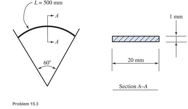
Ch. 15 - A 14 in.-diameter aluminum rod is bent into a...Ch. 15 - 15.2 Calculate the maximum bending stress produced...Ch. 15 - A 500 -mm-long steel bar having a cross section of...Ch. 15 - 15.4 An aluminum wire has a diameter of in....Ch. 15 - 15.5 A -in.-wide by in.-thick board is bent to a...Ch. 15 - 15.6 A Douglas fir beam is in. wide and in. deep....Ch. 15 - Prob. 15.7PCh. 15 - For Problems 15.7 through 15.14, use the formula...Ch. 15 - For Problems 15.7 through 15.14, use the formula...Ch. 15 - For Problems 15.7 through 15.14, use the formula...
Ch. 15 - For Problems 15.7 through 15.14, use the formula...Ch. 15 - For Problems 15.7 through 15.I4, use the formula...Ch. 15 - For Problems 15.7 through 15.14, use the formula...Ch. 15 - For Problems 15.7 through 15.14, use the formula...Ch. 15 - For Problems 15.15 through 15.26, use the...Ch. 15 - For Problems 15.15 through 15.26, use the...Ch. 15 - For Problems 15.15 through 15.26, use the...Ch. 15 - For Problems 15.15 through 15.26, use the...Ch. 15 - For Problems 15.15 through 15.26, use the...Ch. 15 - For Problems 15.15 through 15.26, use the...Ch. 15 - For Problems 15.15 through 15.26, use the...Ch. 15 - For Problems 15.15 through 15.26, use the...Ch. 15 - For Problems 15.15 through 15.26, use the...Ch. 15 - For Problems 15.15 through 15.26, use the...Ch. 15 - For Problems 15.15 through 15.26, use the...Ch. 15 - For Problems 15.15 through 15.26, use the...Ch. 15 - 15.27 Draw the moment diagram by parts for the...Ch. 15 - 15.28 Draw the moment diagram by parts for the...Ch. 15 - 15.29 Draw the moment diagram by parts for the...Ch. 15 - 15.30 For the beam shown, draw the conventional...Ch. 15 - For Problems 15.31 through 15.43, use the...Ch. 15 - For Problems 15.31 through 15.43, use the...Ch. 15 - For Problems 15.31 through 15.43, use the...Ch. 15 - For Problems 15.31 through 15.43, use the...Ch. 15 - For Problems 15.31 through 15.43, use the...Ch. 15 - For Problems 15.31 through 15.43, use the...Ch. 15 - For Problems 15.31 through 15.43, use the...Ch. 15 - For Problems 15.31 through 15.43, use the...Ch. 15 - For Problems 15.31 through 15.43, use the...Ch. 15 - For Problems 15.31 through 15.43, use the...Ch. 15 - For Problems 15.31 through 15.43, use the...Ch. 15 - For Problems 15.31 through 15.43, use the...Ch. 15 - For Problems 15.31 through 15.43, use the...Ch. 15 - 15.49 If the elastic limit of a steel wire is...Ch. 15 - 15.50 Calculate the bending moment required to...Ch. 15 - 15.51 A 6-ft-long cantilever beam is subjected to...Ch. 15 - 15.52 A structural steel wide-flange section is...Ch. 15 - 15.53 A simply supported structural steel...Ch. 15 - 15.54 A structural steel wide-flange shape is...Ch. 15 - A solid, round simply supported steel shaft is...Ch. 15 - Using the moment-area method, check the...Ch. 15 - 15.57 A 1-in.-diameter steel bar is 25 ft long and...Ch. 15 - 15.58 A 102-mm nominal diameter standard-weight...Ch. 15 - I 5.59 Compute the maximum deflection for the...Ch. 15 - An 8-in-wide by 12-in-deep redwood timber beam...Ch. 15 - 15.61 A solid steel shaft 3 in. in diameter and 20...Ch. 15 - 15.62 For the beam shown, draw the conventional...Ch. 15 - 15.63 Rework Problem 15.62 with concentrated loads...Ch. 15 - 15.64 A solid steel shaft 3 in. in diameter and 20...Ch. 15 - 15.65 A structural steel wide-flange section is...Ch. 15 - 15.66 A 6-in.-by-10-in, hem-fir timber beam (S4S)...Ch. 15 - 15.67 A simply supported structural steel...Ch. 15 - Calculate the maximum permissible span length for...Ch. 15 - 15.69 A structural steel wide-flange section 10 ft...Ch. 15 - 15.70 A structural steel wide-flange section...Ch. 15 - 15.71 Determine the deflection at point C and...Ch. 15 - 15.72 Calculate the deflection midway between the...Ch. 15 - 15.73 Derive an expression for the maximum...Ch. 15 - 15.74 Derive an expression for the maximum...
Additional Engineering Textbook Solutions
Find more solutions based on key concepts
Determine its density in SI units. Use an appropriate prefix.
INTERNATIONAL EDITION---Engineering Mechanics: Statics, 14th edition (SI unit)
When force P is applied to the rigid arm ABC, point B displaces vertically downward through a distance of 0.2 m...
Mechanics of Materials
A certain medium lubricating oil has a specific weight of at 8.860kN/m3 at 5 C and 8.483kN/m3 at 50 C. Calculat...
Applied Fluid Mechanics (7th Edition)
The horizontal and the vertical components of force at the pins A and D.
Engineering Mechanics: Statics & Dynamics (14th Edition)
The 60-mm-diameter steel shaft is subjected to the torques shown. Determine the angle of twist of end A with re...
Statics and Mechanics of Materials (5th Edition)
ICA 8-54
When we drive our car at 100 feet per second [ft/s], we measure an aerodynamic force (called drag) of ...
Thinking Like an Engineer: An Active Learning Approach (3rd Edition)
Knowledge Booster


Learn more about
Need a deep-dive on the concept behind this application? Look no further. Learn more about this topic, mechanical-engineering and related others by exploring similar questions and additional content below.Similar questions
- -15 A composite beam is constructed froma wood beam (3 in. x 6 in.) and a steel plate (3 in, wide). The wood and the steel are securely fastened to act as a single beam. The beam is subjected to a positive bending moment M. = 75 kip-in. Calculate the required thickness of the steel plate based on the following limit states: Allowable compressive stress in the wood = 2 ksi Allowable tensile stress in the wood = 2 ksi Allowable tensile stress in the steel plate = 16 ksi Assume that Ew= 1,500 ksi and es= 30,000 ksi.arrow_forwardA r o lukI f/frm f «m t ub e of ou t sid e d ia met er ^ and a copper core of diameter dxare bonded to form a composite beam, as shown in the figure, (a) Derive formulas for the allowable bending moment M that can be carried by the beam based upon an allowable stress <7Ti in the titanium and an allowable stress (u in the copper (Assume that the moduli of elasticity for the titanium and copper are Er- and £Cu, respectively.) (b) If d1= 40 mm, d{= 36 mm, ETl= 120 GPa, ECu= 110 GPa, o-Ti = 840 MPa, and ctqj = 700 MPa, what is the maximum bending moment Ml (c) What new value of copper diameter dtwill result in a balanced design? (i.e., a balanced design is that in which titanium and copper reach allow- able stress values at the same time).arrow_forwardA thin, high-strength steel rule (E = 30 x 10ft psi) having a thickness t = 0.175 in. and length L = 48 in. is bent by couples Mcinto a circular arc subtending a central angle a = 40° (sec figure), What is the maximum bending stress emax. in the rule? By what percent docs the stress increase or decrease if the central angle is increased by 10%? What percent increase or decrease in rule thickness will result in the maximum stress reaching the allowable value of 42 ksi?arrow_forward
- A tie-down on the deck of a sailboat consists of a bent bar boiled at both ends, as shown in the figure. The diameter dBof the bar is 1/4 in., the diameter D Wof the washers is 7/8 in., and the thickness is of the fiberglass deck is 3/8 in. If the allowable shear stress in the fiberglass is 300 psi, and the allowable bearing pressure between the washer and the fiberglass is 550 psi, what is the allowable load P allowon the tie-down?arrow_forwardA cantilever beam of length L = 2 m supports a load P = 8,0 kN (sec figure). The beam is made of wood with cross-sectional dimensions 120 mm x 200 mm. Calculate the shear stresses due to the load/"at points located 25 mm, 50 mm, 75 mm, and 100 mm from the top surface of the beam. From these results, plot a graph showing the distribution of shear stresses from top to bottom of the beam.arrow_forwardCalculate the distance e from the cent crime of the web of a C 15 x 40 channel section to the shear center 5 (see figure). Note: For purposes of analysis, consider the flanges to be rectangles with thickness teequal to the average flange thickness given in Table F-3(a) in Appendix F.arrow_forward
- A seesaw weighing 3 lb/ft of length is occupied by two children, each weighing 90 lb (see figure). The center of gravity of each child is 8 ft from the fulcrum. The board is 19 ft long, 8 in. wide, and 1.5 in. thick. What is the maximum bending stress in the board?arrow_forwardCalculate the distance e from the centerline of the web of a C 310 × 45 channel section to the shear center E (see figure). Note: For put poses of analysis, consider the flanges to be rectangles with thickness îrequal to the average flange thickness given in Table F-3(b) in Appendix F.arrow_forwardA solid circular bar of copper (G = 45 GPa) with length L = 315n m and diameter d = 40 mm is subjected to pure torsion by torques T acting at the ends (see figure). Calculate the amount of strain energy U stored in the bar when the maximum shear stress is 32 MPa. From the strain energy, calculate the angle of twist (in degrees).arrow_forward
- A steel bar 140mm diameter is used to support a pulley block.if the bar is simply supported over a span of 1.4m, calculate the maximum bending stress in the material when the pulley block is at mid span supporting a load of 24KNarrow_forwardQUESTION 2 A rectangular strip of metal 5 mm thick is wound on a circular drum 1.4 m in diameter. If E for the metal is 120 GPa, 2.1 Calculate the maximum bending stress induced in the strip.arrow_forwardThe cross-section of a rectangular beam 25 mm by 72 mm and is subjected to a combined loading of 65 kN direct load and 315 Nm bending load. Calculate the maximum stress due to the combined loading in Figure Q1.arrow_forward
arrow_back_ios
SEE MORE QUESTIONS
arrow_forward_ios
Recommended textbooks for you
 Mechanics of Materials (MindTap Course List)Mechanical EngineeringISBN:9781337093347Author:Barry J. Goodno, James M. GerePublisher:Cengage Learning
Mechanics of Materials (MindTap Course List)
Mechanical Engineering
ISBN:9781337093347
Author:Barry J. Goodno, James M. Gere
Publisher:Cengage Learning
Types of Manufacturing Process | Manufacturing Processes; Author: Magic Marks;https://www.youtube.com/watch?v=koULXptaBTs;License: Standard Youtube License