(a)
Find the value of
(a)
Answer to Problem 15E
The value of
Explanation of Solution
Given data:
Refer to Figure 15.53 in the textbook.
The transfer function of the circuit in Figure 15.53 is,
Formula used:
Write the expression to calculate the impedance of the passive elements resistor, inductor and capacitor in s-domain.
Here,
Calculation:
Given series RLC circuit is drawn as Figure 1.
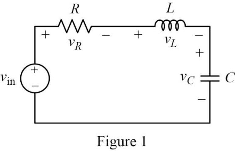
The Figure 1 is redrawn as impedance circuit in s-domain in Figure 2 using the equations (2), (3) and (4).
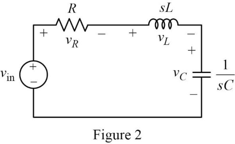
Write the general expression to calculate the transfer function of the circuit in Figure 2.
Here,
Apply Kirchhoff’s voltage law on Figure 2 to find
Rearrange the above equation to find
Substitute
Compare the above equation with the equation (1) to obtain the following values.
Rearrange the equation (6).
Rearrange the above equation to find
Rearrange the equation (7) to find
Substitute
Conclusion:
Thus, the value of
(b)
Find the values of inductor
(b)
Answer to Problem 15E
The value of inductor
Explanation of Solution
Given data:
The value of the resistor
The value of the resonant frequency
Calculation:
Case (i):
From part (a),
Substitute
Rearrange the above equation to find
Rearrange the above equation to find
Rearrange the equation (9).
Rearrange the above equation to find
Substitute
Rearrange the above equation to find
Take square root on both sides of the above equation to find
Substitute
Case (ii):
Substitute
Rearrange the above equation to find
Rearrange the above equation to find
Substitute
Rearrange the above equation to find
Take square root on both sides of the above equation to find
Substitute
Case (iii):
Substitute
Rearrange the above equation to find
Rearrange the above equation to find
Substitute
Rearrange the above equation to find
Take square root on both sides of the above equation to find
Substitute
Conclusion:
Thus, the value of inductor
(c)
Construct the magnitude Bode plots for the three cases
(c)
Explanation of Solution
Calculation:
Simplify the equation (1) to find
Case (i):
Substitute
Case (ii):
Substitute
Case (iii):
Substitute
The equations (15), (16) and (17) are the transfer function of the given series RLC circuit at three different cases
The MATLAB code is given below to sketch the magnitude Bode plots for the three cases using the equations (15), (16) and (17).
MATLAB Code:
clc;
clear all;
close all;
sys1=tf([(4*10^6)],[1 400 (4*10^6)]);
sys2=tf([(4*10^6)],[1 2000 (4*10^6)]);
sys3=tf([(4*10^6)],[1 4000 (4*10^6)]);
bode(sys1,sys2,sys3)
legend({'sys1','sys2','sys3'},'Location','best')
Output:
The MATLAB output Bode plot of the three transfer functions is shown Figure 1.
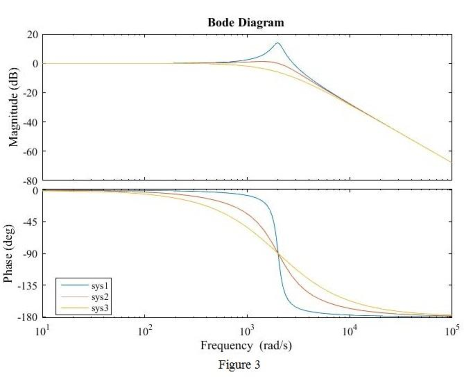
Conclusion:
Thus, the magnitude Bode plot for the three cases
Want to see more full solutions like this?
Chapter 15 Solutions
Loose Leaf for Engineering Circuit Analysis Format: Loose-leaf

- y[n]+1.2y[n-1]+0.2y[n-2]=x[n]-0.5x[n-1] x[n] is system's input, y[n] is system's output. a) Find the transfer function of the system, H(z). Show the region of convergence by drawing the zero-pole diagram. b) Draw the block diagram representation of the system. c) Find h[n], which is the impulse response of the system. d) Is the frequency response H(e^jw) defined for this system? H(e^jw) if defined?arrow_forwardGiven a network with the following transfer function, G(s) = 800(s + 0.5)/ s(s + 100)(s + 2)2 Construct the Bode magnitude and phase plots for the network.arrow_forwardMeasurements conducted on a servomechanism show the system response to be: C (t) = 0.3 e 60t + 1.5 e 10t, when subjected to a unit step input. [1].Obtain the expression for the closed-loop transfer function. [2].Determine the undamped natural frequency and damping ratio of the system.arrow_forward
- Consider the 2nd-order systemH(z) = 1(1 − rejθz−1)(1 − re−jθz−1) find the impulse response h[n] using partial fraction expansion method.arrow_forwardIn the system given with the transfer function G(s)=10/(s+10), when the input value is a unit step,Calculate the time constant Tc, the rise time Tr, and the setting time Ts.arrow_forwardA circuit with a resistor and capacitor in series is subjected to a number of different input voltages as shown in attached image: 1. Derive the transfer function, G(s) of the system using v(s) as the input and vc(s) as the output.arrow_forward
- An input, r(t), defined asr(t) = 0, t < 0r(t) 3.0 t >0is applied to a system that can be described by a transfer function, T(p), whereT(p) = (24p + 208)/(p2+12p+52)Determine the system response, y(t), and sketch the output waveform.arrow_forwardGiven an LTI system with the transfer function H(jΩ)= e-jΩ (2+2cosΩ), the input signal X(n)=4+3cos(π/3n-π/2) + 3cos (20π/21n). (Ω=2πF,F=digital frequency) 1. Find h(n), the impulse response of the filter. 2. Find H(z), the system function of the filter.arrow_forwardFor the circuit of Fig. 10.5, if is=5cos 10t A. use a suitable complex source replacement to obtain a steady- state expression for iL (t).arrow_forward
- Control system Draw the Ver Curve of the Roots for the system given by the following open convolution transfer function: G(s) = s + 0.5➗ S^3 + 8s^2+ 17s + 10arrow_forwardMany chemical processes can be modeled by the following transfer functions: G(s)=[K/(Js+1)] . e^-Tds Where K is the gain, J is the time constant, and Td is the time delay. Obtain the transfer function for the system in terms of the system parameters. Assume that the time delay Td is a multiple of the sample time T.arrow_forwardR = 0.5 C = 0.5 Let the transfer function a driver be denoted as ,arrow_forward
 Introductory Circuit Analysis (13th Edition)Electrical EngineeringISBN:9780133923605Author:Robert L. BoylestadPublisher:PEARSON
 Delmar's Standard Textbook Of ElectricityElectrical EngineeringISBN:9781337900348Author:Stephen L. HermanPublisher:Cengage Learning
 Programmable Logic ControllersElectrical EngineeringISBN:9780073373843Author:Frank D. PetruzellaPublisher:McGraw-Hill Education
 Fundamentals of Electric CircuitsElectrical EngineeringISBN:9780078028229Author:Charles K Alexander, Matthew SadikuPublisher:McGraw-Hill Education
 Electric Circuits. (11th Edition)Electrical EngineeringISBN:9780134746968Author:James W. Nilsson, Susan RiedelPublisher:PEARSON
 Engineering ElectromagneticsElectrical EngineeringISBN:9780078028151Author:Hayt, William H. (william Hart), Jr, BUCK, John A.Publisher:Mcgraw-hill Education,