
EBK MECHANICS OF MATERIALS
7th Edition
ISBN: 9780100257061
Author: BEER
Publisher: YUZU
expand_more
expand_more
format_list_bulleted
Videos
Textbook Question
Chapter 1.5, Problem 54P
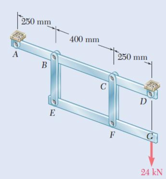
Solve Prob. 1.53, assuming that the pins at C and F have been replaced by pins with a 30-mm diameter.
1.53 Each of the two vertical links CF connecting the two horizontal members AD and EG has a 10 × 40-mm uniform rectangular cross section and is made of a steel with an ultimate strength in tension of 400 MPa, while each of the pins at C and F has a 20-mm diameter and are made of a steel with an ultimate strength in shear of 150 MPa. Determine the overall factor of safety for the links CF and the pins connecting them to the horizontal members.
Fig. P1.53
Expert Solution & Answer
Want to see the full answer?
Check out a sample textbook solution
Students have asked these similar questions
6.
320 lb
The frame ACD is supported by ball-and-socket joints at A and D and by a cable that passes
through a ring at B and is attached to hooks at G and H. Knowing that the frame supports at
point C a load of magnitude P= 268 N, determine the tension in the cable.
0.925 m
0.35 m
0.5 m
B
0.5 m
3 of 3
0.875 m
P
H
0.75 m
0.75 m
x
Question 2
The rods BE and CD are made from steel (E=200 GPa), and each have a diameter, P. The ends
of the rods are threaded with a pitch, p. The nuts at B and C are initially finger tightened such
that they barely touch rigid member ABC. If the nut at C is then tightened by one full turn,
determine:
(a) the tension in rods BE and CD
(b) the distance, uc, that point C on the rigid member ABC moves.
Assume a=300 mm, b= 100 mm, c= 2.5 m, d= 6 m, 0=40 mm, and p=1 mm.
OA
a
В
E
b
D
C
d
Question 2
The rods BE and CD are made from steel (E=200 GPa), and each have a diameter, 0. The ends
of the rods are threaded with a pitch, p. The nuts at B and C are initially finger tightened such
that they barely touch rigid member ABC. If the nut at C is then tightened by one full turn,
determine:
(a) the tension in rods BE and CD
(b) the distance, uc, that point C on the rigid member ABC moves.
Assume a=150 mm, b= 100 mm, c= 2 m, d= 3 m, =16 mm, and p=2.5 mm.
OA
a
В
E
D
C
с
d
Drawing is not to scale.
Chapter 1 Solutions
EBK MECHANICS OF MATERIALS
Ch. 1.2 - Two solid cylindrical rods AB and BC are welded...Ch. 1.2 - Two solid cylindrical rods AB and BC are welded...Ch. 1.2 - Two solid cylindrical rods AB and BC are welded...Ch. 1.2 - Two solid cylindrical rods AB and BC are welded...Ch. 1.2 - A strain gage located at C on the surface of bone...Ch. 1.2 - Two brass rods AB and BC, each of uniform...Ch. 1.2 - Each of the four vertical links has an 8 36-mm...Ch. 1.2 - Link AC has a uniform rectangular cross section 18...Ch. 1.2 - Three forces, each of magnitude P = 4 kN, are...Ch. 1.2 - Link BD consists of a single bar 1 in. wide and 12...
Ch. 1.2 - For the Pratt bridge truss and loading shown,...Ch. 1.2 - The frame shown consists of four wooden members,...Ch. 1.2 - An aircraft tow bar is positioned by means of a...Ch. 1.2 - Two hydraulic cylinders are used to control the...Ch. 1.2 - Determine the diameter of the largest circular...Ch. 1.2 - Two wooden planks, each 12 in. thick and 9 in....Ch. 1.2 - When the force P reached 1600 lb, the wooden...Ch. 1.2 - A load P is applied to a steel rod supported as...Ch. 1.2 - The axial force in the column supporting the...Ch. 1.2 - Three wooden planks are fastened together by a...Ch. 1.2 - A 40-kN axial load is applied to a short wooden...Ch. 1.2 - An axial load P is supported by a short W8 40...Ch. 1.2 - Link AB, of width b = 2 in. and thickness t=14...Ch. 1.2 - Determine the largest load P that can be applied...Ch. 1.2 - Knowing that = 40 and P = 9 kN, determine (a) the...Ch. 1.2 - The hydraulic cylinder CF, which partially...Ch. 1.2 - For the assembly and loading of Prob. 1.7,...Ch. 1.2 - Two identical linkage-and-hydraulic-cylinder...Ch. 1.5 - Two wooden members of uniform rectangular cross...Ch. 1.5 - Two wooden members of uniform rectangular cross...Ch. 1.5 - The 1.4-kip load P is supported by two wooden...Ch. 1.5 - Two wooden members of uniform cross section are...Ch. 1.5 - A centric load P is applied to the granite block...Ch. 1.5 - A 240-kip load P is applied to the granite block...Ch. 1.5 - A steel pipe of 400-mm outer diameter is...Ch. 1.5 - A steel pipe of 400-mm outer diameter is...Ch. 1.5 - A steel loop ABCD of length 5 ft and of 38-in....Ch. 1.5 - Link BC is 6 mm thick, has a width w = 25 mm, and...Ch. 1.5 - Link BC is 6 mm thick and is made of a steel with...Ch. 1.5 - Members AB and BC of the truss shown are made of...Ch. 1.5 - Members AB and BC of the truss shown are made of...Ch. 1.5 - Link AB is to be made of a steel for which the...Ch. 1.5 - Two wooden members are joined by plywood splice...Ch. 1.5 - For the joint and loading of Prob. 1.43, determine...Ch. 1.5 - Three 34-in.-diameter steel bolts are to be used...Ch. 1.5 - Three steel bolts are to be used to attach the...Ch. 1.5 - A load P is supported as shown by a steel pin that...Ch. 1.5 - A load P is supported as shown by a steel pin that...Ch. 1.5 - A steel plate 14 in. thick is embedded in a...Ch. 1.5 - Determine the factor of safety for the cable...Ch. 1.5 - Link AC is made of a steel with a 65-ksi ultimate...Ch. 1.5 - Solve Prob. 1.51, assuming that the structure has...Ch. 1.5 - Each of the two vertical links CF connecting the...Ch. 1.5 - Solve Prob. 1.53, assuming that the pins at C and...Ch. 1.5 - In the structure shown, an 8-mm-diameter pin is...Ch. 1.5 - In an alternative design for the structure of...Ch. 1.5 - Prob. 57PCh. 1.5 - The Load and Resistance Factor Design method is to...Ch. 1 - In the marine crane shown, link CD is known to...Ch. 1 - Two horizontal 5-kip forces are applied to pin B...Ch. 1 - For the assembly and loading of Prob. 1.60,...Ch. 1 - Two steel plates are to be held together by means...Ch. 1 - A couple M of magnitude 1500 N m is applied to...Ch. 1 - Knowing that link DE is 18 in. thick and 1 in....Ch. 1 - A 58-in.-diameter steel rod AB is fitted to a...Ch. 1 - In the steel structure shown, a 6-mm-diameter pin...Ch. 1 - Prob. 67RPCh. 1 - A force P is applied as shown to a steel...Ch. 1 - The two portions of member AB are glued together...Ch. 1 - The two portions of member AB are glued together...
Knowledge Booster


Learn more about
Need a deep-dive on the concept behind this application? Look no further. Learn more about this topic, mechanical-engineering and related others by exploring similar questions and additional content below.Similar questions
- Question 2 The rods BE and CD are made from steel (E=200 GPa), and each have a diameter, 0. The ends of the rods are threaded with a pitch, p. The nuts at B and C are initially finger tightened such that they barely touch rigid member ABC. If the nut at C is then tightened by one full turn, determine: (a) the tension in rods BE and CD (b) the distance, uc, that point C on the rigid member ABC moves. Assume a=150 mm, b= 100 mm, c= 2 m, d= 3 m, D=16 mm, and p=2.5 mm. A a В E D C d Drawing is not to scale.arrow_forward1.18 Determine the smallest safe cross-sectional areas of members CD, GD, and GF for the truss shown. The working stresses are 140 MPa in tension and 100 MPa in compression. (The working stress in compression is smaller to reduce the danger of buckling.) B 6 m 4 m 4m E 6 m H 6 m Ġ 6m F 6m 140 kN 140 kN A.arrow_forwardEach of the two vertical links CF connecting the two horizontal members AD and EG has a 10x40-mm uniform rectangular cross section and is made of a steel with an ultimate strength in tension of 400 MPa,while each of the pins at C and F has a 20-mm diameter and is made of a steel with an ultimate strength in shear of 150 MPa. Determine the overall factor of safety for the links CF and the pins connecting them to the horizontal members.arrow_forward
- Member ABC, which is supported by a pin and bracket at C and a cable BD, was designed to support the 20-kN load P as shown. The pin at C has 20 mm diameter. a) Draw complete free body diagram of member ABC and determine all forces acting upon it b) If pin at C was made from steel with ultimate shear stress 300 MPa, calculate its factor of safety c) Knowing that rope BD made of a material has allowable stress of 50 MPa, calculate its diameter d) Use the information in part c, find the Young’s modulus of the rope material knowing that its length is 0.5 m and stretched by 0.5 mm upon the shown loading.arrow_forwardA 20 mm diameter rod BC has flat ends of 20 mm x 40 mm rectangular cross section, while the boom AB has a 30 x 50 mm rectangular cross section and is fitted with a clevis at the end B. Both members are connected at B by a pin from which the 30 kN load is suspended by means of a U-Shaped bracket. Boom AB is supported at A by a pin fitted into a double bracket, while rod BC is connected at C to a single bracket. All pins are 25 mm diameter. Determine the normal stresses in members AB and BC; shearing stresses and bearing stresses at A, B and C.arrow_forwardTwo cylindrical rods, one of steel and the other of brass, are joined at C and restrained by rigid supports at A and E. The steel rod has a length of 300 mm while the brass rod has a length of 200 mm. The diameters of the rods are shown in the figure below. A force of 60 kN is applied at point B of the steel segment. For the loading shown and knowing that modulus of elasticity values for steel and brass are respectively Es = 200 GPa and Eb = 105 GPa, determine a.) The reactions at A and E: RA and RE. b.) The deflection of point C from its original location. how to doarrow_forward
- 5. A bronze rod is rigidly attached between a aluminum rod and a steel rod as shown. Axial loads are applied at the positions indicated. Find the maximum allowable value of P that will not exceed a stress in steel of 140MPa, in aluminum of 90MPa or in bronze of 100MPa.arrow_forwardProblem 1. The steel tie bar shown is to be designed to carry a tension force of magnitude P = 130KN when bolted between double brackets at A and B. The bar will be fabricated from 25-mm-thick plate stock. For the grade of steel to be used, the maximum allowable stresses are: o = 170 MPa, t = 110 MPa, op = 370 MPa. Design the tie bar by determining the required values of: a. the diameter d of the bolt, b. the dimension b at each end of the bar, c. the dimensionh of the bar.arrow_forwardProblem 5 Rigid member ABC is supported with two links BE and CD which have a cross section area of 230 and 300 mm? respectively. Determine the maximum applied force Q knowing that the maximum movement of point E is 0.45 mm. D Brass E - 105 GPa 230 mm B C E Aluminum E = 70 GPa 150 mm 65 mm 230 mm Area given is for member AB not BE Cross section area of links AB and CD are 230 and 300 mm^2 respectively.arrow_forward
- Mechanics of Deformable Bodies. Eight steel cables (with equal distance to each other) are supporting a circular heavy moulding of diameter 3m from an overhead point. If the moulding weighs 5 kN/m and the attachment point is 4m above it, determine the following: a. Calculate the tension of the cable. b. Determine the diameter of the wire if the allowable stress is 125 MPa. c. If the diameter of the cable is 10 mm, find the deflection of the steel cable. d. If the diameter of the cable is 10 mm, find the vertical displacement of the molder.arrow_forwardThe boom AB is made up of a hollow square 100-mm tube having a wall thickness of 5 mm. A 10-mm diameter steel cable BC and a 16-mm diameter pin at A support the boom in the position shown. The working stresses are 170 MPa for the cable, 124 MPa for the boom, and 94 MPa for shear in the pin. Neglecting the weight of the boom, determine the largest safe load W that can be applied asarrow_forwardThe boom AB is made up of a hollow square 80-mm tube having a wall thickness of 2 mm. A 20-mm diameter steel cable BC and a 16-mm diameter pin at A support the boom in the position shown. The working stresses are 140 MPa for the cable, 110 MPa for the boom, and 70 MPa for shear in the pin. Neglecting the weight of the boom, determine the largest safe load W that can be applied as shown.arrow_forward
arrow_back_ios
SEE MORE QUESTIONS
arrow_forward_ios
Recommended textbooks for you
 Elements Of ElectromagneticsMechanical EngineeringISBN:9780190698614Author:Sadiku, Matthew N. O.Publisher:Oxford University Press
 Mechanics of Materials (10th Edition)Mechanical EngineeringISBN:9780134319650Author:Russell C. HibbelerPublisher:PEARSON
 Thermodynamics: An Engineering ApproachMechanical EngineeringISBN:9781259822674Author:Yunus A. Cengel Dr., Michael A. BolesPublisher:McGraw-Hill Education
 Control Systems EngineeringMechanical EngineeringISBN:9781118170519Author:Norman S. NisePublisher:WILEY
 Mechanics of Materials (MindTap Course List)Mechanical EngineeringISBN:9781337093347Author:Barry J. Goodno, James M. GerePublisher:Cengage Learning
 Engineering Mechanics: StaticsMechanical EngineeringISBN:9781118807330Author:James L. Meriam, L. G. Kraige, J. N. BoltonPublisher:WILEY
Elements Of Electromagnetics
Mechanical Engineering
ISBN:9780190698614
Author:Sadiku, Matthew N. O.
Publisher:Oxford University Press
Mechanics of Materials (10th Edition)
Mechanical Engineering
ISBN:9780134319650
Author:Russell C. Hibbeler
Publisher:PEARSON
Thermodynamics: An Engineering Approach
Mechanical Engineering
ISBN:9781259822674
Author:Yunus A. Cengel Dr., Michael A. Boles
Publisher:McGraw-Hill Education
Control Systems Engineering
Mechanical Engineering
ISBN:9781118170519
Author:Norman S. Nise
Publisher:WILEY
Mechanics of Materials (MindTap Course List)
Mechanical Engineering
ISBN:9781337093347
Author:Barry J. Goodno, James M. Gere
Publisher:Cengage Learning
Engineering Mechanics: Statics
Mechanical Engineering
ISBN:9781118807330
Author:James L. Meriam, L. G. Kraige, J. N. Bolton
Publisher:WILEY
An Introduction to Stress and Strain; Author: The Efficient Engineer;https://www.youtube.com/watch?v=aQf6Q8t1FQE;License: Standard YouTube License, CC-BY