
Statics and Mechanics of Materials, Student Value Edition (5th Edition)
5th Edition
ISBN: 9780134382890
Author: Russell C. Hibbeler
Publisher: PEARSON
expand_more
expand_more
format_list_bulleted
Videos
Textbook Question
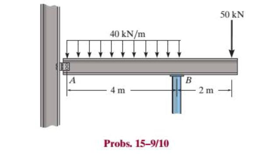
Chapter 15.2, Problem 10P
Investigate if the W250 × 58 beam can safely support the loading. The beam has an allowable normal stress of σallow = 150 MPa and an allowable shear stress of τallow = 80 MPa. Assume there is a pin at A and a roller support at B.
Expert Solution & Answer
Want to see the full answer?
Check out a sample textbook solution
Students have asked these similar questions
The simply supported joist is used in the construction of a floor for a building. In order to keep the floor low with respect to the sill beams C and D, the ends of the joist are notched as shown. If the allowable shear stress is tallow = 350 psi and the allowable bending stress is s allow = 1700 psi, determine the smallest height h so that the beam will support a load of P = 600 lb. Also, will the entire joist safely support the load? Neglect the stress concentration at the notch.
Determine the shear stress (in Mpa) in the 28.54-mm-diameter pin at B that support the beam if P = 35.79 kN, a = 2.76 m, and b = 5.95 m.
Determine the shear stress (in Mpa) in the 23.5-mm-diameter pin at A that support the beam if P = 28.36 kN, a = 2.25 m, and b = 6.56 m.
Chapter 15 Solutions
Statics and Mechanics of Materials, Student Value Edition (5th Edition)
Ch. 15.2 - Determine the minimum dimension a to the nearest...Ch. 15.2 - Prob. 2FPCh. 15.2 - Prob. 3FPCh. 15.2 - Determine the minimum dimension h to the nearest...Ch. 15.2 - Prob. 5FPCh. 15.2 - Select the lightest W410-shaped section that can...Ch. 15.2 - The beam is made of timber that has an allowable...Ch. 15.2 - Determine the minimum width of the beam to the...Ch. 15.2 - Determine the minimum width of the beam to the...Ch. 15.2 - The brick wall exerts a uniform distributed load...
Ch. 15.2 - Select the lightest-weight wide-flange beam from...Ch. 15.2 - Prob. 6PCh. 15.2 - Select the lightest-weight wide-flange beam with...Ch. 15.2 - Select the lightest-weight wide-flange beam from...Ch. 15.2 - Select the lightest W360 wide-flange beam from...Ch. 15.2 - Investigate if the W250 58 beam can safely...Ch. 15.2 - The beam is constructed from two boards. If each...Ch. 15.2 - The joists of a floor in a warehouse are to be...Ch. 15.2 - The timber beam has a width of 6 in. Determine its...Ch. 15.2 - The beam is constructed from four boards. If each...Ch. 15.2 - The beam is constructed from two boards. If each...Ch. 15.2 - If the cable is subjected to a maximum force of P...Ch. 15.2 - If the W360 45 wide-flange beam has an allowable...Ch. 15.2 - If P = 800 lb, determine the minimum dimension a...Ch. 15.2 - If a = 3 in. and the wood has an allowable normal...Ch. 15.2 - The beam is constructed from three plastic strips....Ch. 15.2 - If the allowable bending stress is allow = 6 MPa,...Ch. 15.2 - The beam is made of Douglas fir having an...Ch. 15.2 - Select the lightest-weight wide-flange beam from...Ch. 15.2 - Draw the shear and moment diagrams for the shaft,...Ch. 15.2 - Draw the shear and moment diagrams for the shaft,...
Knowledge Booster


Learn more about
Need a deep-dive on the concept behind this application? Look no further. Learn more about this topic, mechanical-engineering and related others by exploring similar questions and additional content below.Similar questions
- If a = 3 in. and the wood has an allowable normal stress of sallow = 1.5 ksi, and an allowable shear stress of tallow = 150 psi, determine the maximum allowable value of P that can act on the beam.arrow_forwardQ1/ A composite beam is made of wood and reinforced with steel strap located on its bottom side. It has the cross-sectional area shown in fig. if the beam is subjected to a bending moment of M=2kN.m, determine the normal stress at wood and steel. Take Ew=12Gpa and Est=200Gpa. 150mm Wood en 20mm Steel 150mmarrow_forwardRigid beam AB is supported by three bolts at A and a pin at B. The bolts at A are in double shear and have a diameter of 0.375 in. Assume L = 7.0 ft. If the average shear stress in the bolts cannot exceed 60 ksi, determine the maximum distributed load wmax that can be supported by the structure. (1) Answer: Wmax= i L kips/ftarrow_forward
- All the pins are in double shear, and they each have a diameter of 14 mm. The average shear stress in each pin CANNOT exceed 70 MPa. What is the max magnitude of P that the beam can supportarrow_forwardThe cantilever beam is subjected to a concentrated load of P-32 kips. The cross-sectional dimensions of the rectangular tube shape are b-8.2 in, d - 13.30 in, and t-0.300 in. Determine: (a) the magnitude of the shear stress at point K, which is located to the left of the vertical centroidal axis at zx = 1.7 in. (b) the magnitude of the maximum horizontal shear stress in the rectangular tube shape. Answer: (a) Ti (b) Tmax= x ksi ksi (typ.) TK b エーミー H darrow_forwardRigid beam AB is supported by three bolts at A and a pin at B. The bolts at A are in double shear and have a diameter of 0.375 in. Assume L = 5.0 ft. If the average shear stress in the bolts cannot exceed 60 ksi, determine the maximum distributed load Wmax that can be supported by the structure. (1) Answer: Wmax = L B kips/ftarrow_forward
- The axle of the freight train is subjected to loadings as shown below. The diameter of the axle is 137.5 mm. If it is supported by two journal bearings at C and D, determine the maximum bending stress. Include a FBD, SFD and BMD using either the section or graphical method. Draw a cross-section of the shaft and indicate the points of maximum tension and compression. A B 250 mm 100 kN 1500 mm- Answer 0= +98 MPa 250 mm 100 kNarrow_forwardThe singular force F will be applied to the beam with a hollow rectangular cross section. Accordingly, the location and value of the maximum normal stress that will occur in the whole beam is given correctly in the following? F =400 N, L1 = 3m, L2 = 2m, h1=48mm, h2 =72mm, b1=10mm, b2=20mmarrow_forwardThe beam is supported by a pin at point A and a roller at kN point B. A distributed load of W₁ = 8 - and an applied m force of F₁ = 12 kN are applied to the beam. The beam has an allowable bending stress of allow = 6 MPa. Neglect the weight and thickness of the beam. Take the origin for all functions to be at A., i.e. start at the left and go right. Must use positive sign convention for V and M. d3 1 d3 d1 W1 d1 B O h d2 F₁ Values for the figure are given in the following table. Note the figure may not be to scale. Dimensions for the whole beam Variable Value d₁ 4 m d₂ 2 marrow_forward
- For the beam and loading shown below, determine the maximum shear stress acting at section a−a. Give your answer in psi.arrow_forwardRigid beam AB is supported by three bolts at A and a pin at B. The bolts at A are in double shear and have a diameter of 0.250 in. Assume L = 3.5 ft. If the average shear stress in the bolts cannot exceed 75 ksi, determine the maximum distributed load wmax that can be supported by the structure. (1) Answer: Wmax i kips/ftarrow_forwardRigid beam AB is supported by three bolts at A and a pin at B. The bolts at A are in double shear and have a diameter of 0.250 in. Assume L = 5.5 ft. If the average shear stress in the bolts cannot exceed 40 ksi, determine the maximum distributed load Wmax that can be supported by the structure. (1) AF₁ tece Answer: Wmax Mi L W B kips/ftarrow_forward
arrow_back_ios
SEE MORE QUESTIONS
arrow_forward_ios
Recommended textbooks for you
 Elements Of ElectromagneticsMechanical EngineeringISBN:9780190698614Author:Sadiku, Matthew N. O.Publisher:Oxford University Press
 Mechanics of Materials (10th Edition)Mechanical EngineeringISBN:9780134319650Author:Russell C. HibbelerPublisher:PEARSON
 Thermodynamics: An Engineering ApproachMechanical EngineeringISBN:9781259822674Author:Yunus A. Cengel Dr., Michael A. BolesPublisher:McGraw-Hill Education
 Control Systems EngineeringMechanical EngineeringISBN:9781118170519Author:Norman S. NisePublisher:WILEY
 Mechanics of Materials (MindTap Course List)Mechanical EngineeringISBN:9781337093347Author:Barry J. Goodno, James M. GerePublisher:Cengage Learning
 Engineering Mechanics: StaticsMechanical EngineeringISBN:9781118807330Author:James L. Meriam, L. G. Kraige, J. N. BoltonPublisher:WILEY
Elements Of Electromagnetics
Mechanical Engineering
ISBN:9780190698614
Author:Sadiku, Matthew N. O.
Publisher:Oxford University Press
Mechanics of Materials (10th Edition)
Mechanical Engineering
ISBN:9780134319650
Author:Russell C. Hibbeler
Publisher:PEARSON
Thermodynamics: An Engineering Approach
Mechanical Engineering
ISBN:9781259822674
Author:Yunus A. Cengel Dr., Michael A. Boles
Publisher:McGraw-Hill Education
Control Systems Engineering
Mechanical Engineering
ISBN:9781118170519
Author:Norman S. Nise
Publisher:WILEY
Mechanics of Materials (MindTap Course List)
Mechanical Engineering
ISBN:9781337093347
Author:Barry J. Goodno, James M. Gere
Publisher:Cengage Learning
Engineering Mechanics: Statics
Mechanical Engineering
ISBN:9781118807330
Author:James L. Meriam, L. G. Kraige, J. N. Bolton
Publisher:WILEY
Mechanics of Materials Lecture: Beam Design; Author: UWMC Engineering;https://www.youtube.com/watch?v=-wVs5pvQPm4;License: Standard Youtube License