
Statics and Mechanics of Materials (5th Edition)
5th Edition
ISBN: 9780134382593
Author: Russell C. Hibbeler
Publisher: PEARSON
expand_more
expand_more
format_list_bulleted
Videos
Textbook Question
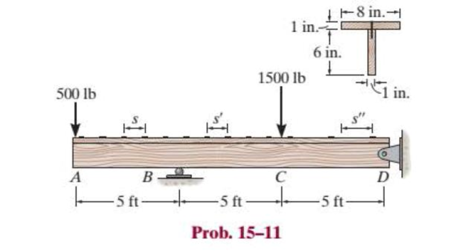
Chapter 15.2, Problem 11P
The beam is constructed from two boards. If each nail can support a shear force of 200 lb, determine the maximum spacing of the nails, s, s′, and s″, to the nearest
Expert Solution & Answer
Want to see the full answer?
Check out a sample textbook solution
Students have asked these similar questions
The boards are bolted together to form the built-up beam. If the beam is subjected to a shear force of V = 15 kip, determine the maximum spacing s of the bolts to the nearest 1 8 in. if each bolt has a shear strength of 6 kip.
Two identical 20-mm-thick plates are bolted to the top and bottom flange to form the built-up beam. If the beam is subjected to a shear force of V = 300 kN, determine the maximum spacing s of the bolts to the nearest mm if eachbolt has a shear strength of 30 kN.
The two identical boards are bolted together to form the beam. Determine the maximum spacing s of the bolts to the nearest mm if each bolt has a shear strength of 15 kN. The beam is subjected to a shear force of V = 50 kN.
Chapter 15 Solutions
Statics and Mechanics of Materials (5th Edition)
Ch. 15.2 - Determine the minimum dimension a to the nearest...Ch. 15.2 - Prob. 2FPCh. 15.2 - Prob. 3FPCh. 15.2 - Determine the minimum dimension h to the nearest...Ch. 15.2 - Prob. 5FPCh. 15.2 - Select the lightest W410-shaped section that can...Ch. 15.2 - The beam is made of timber that has an allowable...Ch. 15.2 - Determine the minimum width of the beam to the...Ch. 15.2 - Determine the minimum width of the beam to the...Ch. 15.2 - The brick wall exerts a uniform distributed load...
Ch. 15.2 - Select the lightest-weight wide-flange beam from...Ch. 15.2 - Prob. 6PCh. 15.2 - Select the lightest-weight wide-flange beam with...Ch. 15.2 - Select the lightest-weight wide-flange beam from...Ch. 15.2 - Select the lightest W360 wide-flange beam from...Ch. 15.2 - Investigate if the W250 58 beam can safely...Ch. 15.2 - The beam is constructed from two boards. If each...Ch. 15.2 - The joists of a floor in a warehouse are to be...Ch. 15.2 - The timber beam has a width of 6 in. Determine its...Ch. 15.2 - The beam is constructed from four boards. If each...Ch. 15.2 - The beam is constructed from two boards. If each...Ch. 15.2 - If the cable is subjected to a maximum force of P...Ch. 15.2 - If the W360 45 wide-flange beam has an allowable...Ch. 15.2 - If P = 800 lb, determine the minimum dimension a...Ch. 15.2 - If a = 3 in. and the wood has an allowable normal...Ch. 15.2 - The beam is constructed from three plastic strips....Ch. 15.2 - If the allowable bending stress is allow = 6 MPa,...Ch. 15.2 - The beam is made of Douglas fir having an...Ch. 15.2 - Select the lightest-weight wide-flange beam from...Ch. 15.2 - Draw the shear and moment diagrams for the shaft,...Ch. 15.2 - Draw the shear and moment diagrams for the shaft,...
Knowledge Booster


Learn more about
Need a deep-dive on the concept behind this application? Look no further. Learn more about this topic, mechanical-engineering and related others by exploring similar questions and additional content below.Similar questions
- The beam is constructed from two boards fastened together at the top and bottom with three rows of nails spaced every 8 in. If an internal shear force of V = 800 lb is applied to the boards, determine the shear force resisted by each nail.arrow_forwardThe box beam is constructed from four boards that are fastened together using nails spaced along the beam every 2 in. If a force P = 2 kip is applied to the beam, determine the shear force resisted by each nail at A and B.arrow_forwardThe built-up beam is formed by welding together the thin plates of thickness 5 mm. Determine the location of the shear center Oarrow_forward
- The corners of the square plate are given the displacements indicated. Determine the shear strain at A relative to axes that are directed along with AB and AD, and the shear strain at B relative to axes that are directed along with BC and BA.arrow_forwardThe simply supported beam is built up from three boards by nailing them together as shown. If P = 12 kN, determine the maximum allowable spacing s of the nails to support that load, if each nail can resist a shear force of 1.5 kN.arrow_forwardDetermine the maximum absolute value of the shear.arrow_forward
- The box beam is constructed from four boards that are fastened together using nails spaced along the beam every 2 in. If each nail can resist a shear force of 50 lb, determine the largest force P that can be applied to the beam without causing failure of the nails.arrow_forwardThe beam supports a vertical shear of V = 7 kip. Determine the resultant force in segment AB of the beam.arrow_forwardThe solid aluminum shaft has a diameter of 50 mm. Determine the absolute maximum shear stress in the shaft and sketch the shear-stress distribution along a radial line of the shaft where the shear stress is maximum. Set T1 = 2000 N # m.arrow_forward
- Determine the maximum shear stress acting in the fiberglass beam at the section where the internal shears force is maximum. (t1=15 mm, t2=20 mm, h=150 mm, b=50mm)arrow_forwardSketch the intensity of the shear-stress distribution acting over the beam’s cross-sectional area, and determine the resultant shear force acting on the segment AB. The shear force acting at the section is V = 35 kip. Show that INA = 872.49 in4.arrow_forwardDetermine the location e of the shear center, point O, for the thin-walled member. The member segments have the same thickness t.arrow_forward
arrow_back_ios
SEE MORE QUESTIONS
arrow_forward_ios
Recommended textbooks for you
 Elements Of ElectromagneticsMechanical EngineeringISBN:9780190698614Author:Sadiku, Matthew N. O.Publisher:Oxford University Press
 Mechanics of Materials (10th Edition)Mechanical EngineeringISBN:9780134319650Author:Russell C. HibbelerPublisher:PEARSON
 Thermodynamics: An Engineering ApproachMechanical EngineeringISBN:9781259822674Author:Yunus A. Cengel Dr., Michael A. BolesPublisher:McGraw-Hill Education
 Control Systems EngineeringMechanical EngineeringISBN:9781118170519Author:Norman S. NisePublisher:WILEY
 Mechanics of Materials (MindTap Course List)Mechanical EngineeringISBN:9781337093347Author:Barry J. Goodno, James M. GerePublisher:Cengage Learning
 Engineering Mechanics: StaticsMechanical EngineeringISBN:9781118807330Author:James L. Meriam, L. G. Kraige, J. N. BoltonPublisher:WILEY
Elements Of Electromagnetics
Mechanical Engineering
ISBN:9780190698614
Author:Sadiku, Matthew N. O.
Publisher:Oxford University Press
Mechanics of Materials (10th Edition)
Mechanical Engineering
ISBN:9780134319650
Author:Russell C. Hibbeler
Publisher:PEARSON
Thermodynamics: An Engineering Approach
Mechanical Engineering
ISBN:9781259822674
Author:Yunus A. Cengel Dr., Michael A. Boles
Publisher:McGraw-Hill Education
Control Systems Engineering
Mechanical Engineering
ISBN:9781118170519
Author:Norman S. Nise
Publisher:WILEY
Mechanics of Materials (MindTap Course List)
Mechanical Engineering
ISBN:9781337093347
Author:Barry J. Goodno, James M. Gere
Publisher:Cengage Learning
Engineering Mechanics: Statics
Mechanical Engineering
ISBN:9781118807330
Author:James L. Meriam, L. G. Kraige, J. N. Bolton
Publisher:WILEY
Mechanics of Materials Lecture: Beam Design; Author: UWMC Engineering;https://www.youtube.com/watch?v=-wVs5pvQPm4;License: Standard Youtube License