
Concept explainers
Videos
Velocity sensors are placed on a satellite that is moving only in the xy plane. Knowing that at the instant shown the unidirectional sensors measure
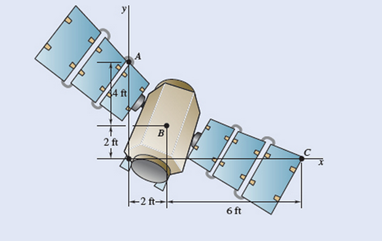
Fig. P15.41
Want to see the full answer?
Check out a sample textbook solution
Chapter 15 Solutions
Vector Mechanics For Engineers


- Knowing that at the instant shown the angular velocity of rod AB is 15 rad/s clockwise, write down the equation of velocity of point B relative to point A. -V_Bi=(-15k)x(-0.2j) +V_Bj=V_Ai-(15k) x (0.6i+0.25j) -V_Bi=V_A+(-15k)x(0.2j) +V_Bj=V_Ai-(omega_BDk) x (-0.6i-0.25j)arrow_forwardIn Prob. 15.14, determine the velocity and acceleration of point E , assuming that the angular velocity is 26 rad/s and increases at the rate of 65 rad/s2.Reference to Problem 15.14:A circular plate of 120-mm radius is supported by two bearings A and B as shown. The plate rotates about the rod joining A and B with a constant angular velocity of 26 rad/s. Knowing that, at the instant considered, the velocity of point C is directed to the right, determine the velocity and acceleration of point E.arrow_forwardIn a four bar mechanism, the dimensions of the links are as given below:AB = 50 mm, BC = 66 mmCD = 56 mm and AD = 100 mmAt a given instant when | DAB=60°the angular velocity of link AB is 10.5rad/sec in CCW direction.Determine,i) Velocity of point Cii) Velocity of point E on link BC when BE = 40 mmiii) The angular velocity of link BC and CDiv) The velocity of an offset point F on link BC, if BF = 45 mm,CF = 30 mm and BCF is read clockwise.v) The velocity of an offset point G on link CD, if CG = 24mm, DG = 44 mm and DCG is read clockwise.vi) The velocity of rubbing of pins A, B, C and D. The ratios ofthe pins are 30 mm, 40 mm, 25 mm and 35 mmrespectively.arrow_forward
- A helicopter moves horizontally in the x direction at a speed of 120 mi/h. Knowing that the main blades rotate clockwise when viewed from above with an angular velocity of 180 rpm, determine the instantaneous axis of rotation of the main blades.arrow_forwardA juggling club is thrown vertically into the air. The center of gravity G of the 20-in. club is located 12 in. from the knob. Knowing that at the instant shown, G has a velocity of 4 ft/s upward and the club has an angular velocity of 30 rad/s counterclockwise, determine (a) the speeds of points A and B, (b) the location of the instantaneous center of rotation.arrow_forwardA painter is half way up a 10-m ladder when the bottom starts sliding out from under him. Knowing that point A has a velocity vA = 2 m/s directed to the left when 0= 60°, determine (a) the angular velocity of the ladder, (b) the velocity of the painter.arrow_forward
- A radar system is used to track a new experimental space launch vehicle. Early in the vehicle’s flight trajectory, the azimuth angle β is increasing with the constant rate dβ/dt = 20°/s. The elevation angle γ is increasing at the rate dγ/dt = 40°/s, and this rate is increasing at 5°/s2 . Knowing that the distance between O and P is 2 m and that at this instant β = 0° and γ = 30°, determine (a) the angular velocity of the radar system, (b) the angular acceleration of the system, and (c) the velocity and acceleration of point P.arrow_forwardThe disk shown moves in the xy plane. Knowing that (vA)y = −7 m/s, (vB)x = −7.4 m/s, and (vC)x = −1.4 m/s, determine (a) the angular velocity of the disk, (b) the velocity of point B.arrow_forwardConsider that at the instant shown, bar AB of the mechanical system below has a angular velocity (wAB) counterclockwise at 5 rad/s and an angular acceleration (alphaAB)counterclockwise 2 rad/s².The length of bar AB is 0.4 m and the length of bar BC is 1 m. For the instant shown, and using a "Analysis of Relative Motion", determine: (a) the speed of point B (b) angular velocity of connecting bar BC (c) the speed of point C (d) the acceleration of point B (d) the acceleration of point Carrow_forward
- In a four-link mechanism, the dimensions of the links are given as AB=50mm, BC=66mm, CD=56mm, and AD=100mm. At the instant when <DAB = 60° , the link AB has an angular velocity of 10.5 rad/sec in the counterclockwise direction. Both A and D lies in the horizontal plane.For the given configuration of the mechanism, determine the following: angular velocity of the link CD, angular velocity of the link BC, velocity of an offset point G on the link CD if CG=24mm,DG=44mm Instructions: configuration diagram Scale: 1:1 velocity diagram. Scale: 1m/s : 95mmarrow_forwardProblem 1: In a four bar mechanism, the dimensions of the links are as given below: AB = 50 mm, BC = 66 mm CD = 56 mm and AD = 100 mm At a given instant when |DAB 60o the angular velocity of link AB is 10.5 r/s in CCW direction. Determine, i) Velocity of point C ii) Velocity of point E on link BC when BE = 40 mm iii) The angular velocity of link BC and CD iv) The velocity of an offset point F on link BC, if BF = 45 mm, CF = 30 mm and BCF is read clockwise. v) The velocity of an offset point G on link CD, if CG = 24 mm, DG = 44 mm and DCG is read clockwise. vi) The velocity of rubbing of pins A, B, C and D. The ratio of the pins are 30 mm, 40 mm, 25 mm and 35 mm respectively.arrow_forwardThe motion of an oscillating flywheel is defined by the relation 0=00e-3πtcos 4, πt where 0 is expressed in radians and t in seconds. Knowing that 00 = 0.5 rad, determine the angular coordinate, the angular velocity, and the angular acceleration of the flywheel when (a) t= 0, (b) t= 0.125 s.arrow_forward
 Elements Of ElectromagneticsMechanical EngineeringISBN:9780190698614Author:Sadiku, Matthew N. O.Publisher:Oxford University Press
 Mechanics of Materials (10th Edition)Mechanical EngineeringISBN:9780134319650Author:Russell C. HibbelerPublisher:PEARSON
 Thermodynamics: An Engineering ApproachMechanical EngineeringISBN:9781259822674Author:Yunus A. Cengel Dr., Michael A. BolesPublisher:McGraw-Hill Education
 Control Systems EngineeringMechanical EngineeringISBN:9781118170519Author:Norman S. NisePublisher:WILEY
 Mechanics of Materials (MindTap Course List)Mechanical EngineeringISBN:9781337093347Author:Barry J. Goodno, James M. GerePublisher:Cengage Learning
 Engineering Mechanics: StaticsMechanical EngineeringISBN:9781118807330Author:James L. Meriam, L. G. Kraige, J. N. BoltonPublisher:WILEY