
Concept explainers
Videos
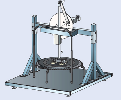
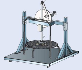
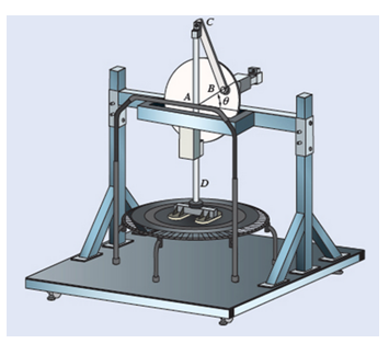
The test rig is shown was developed to perform fatigue testing on fitness trampolines. A motor drives the 9-in.-radius flywheel AB, which is pinned at its center point A, in a counterclockwise direction. The flywheel is attached to slider CD by the 18-in. connecting rod BC. Knowing that the a “feet” at D should hit the trampoline twice every second, at the instant when
Fig. P15.59
(a)
The angular velocity of the connecting rod BC
Answer to Problem 15.59P
The angular velocity of connecting rod BC is
Explanation of Solution
Given information:
Radius of flywheel is
The length of connecting rod BC is
The absolute value of point A
The relative velocity of A with respect to B is defined as
Calculation:
The angular velocity of AB

According to the geometry
Therefore
The position vector of B relative to A
Substitute
The position vector of C relative to B
Substitute
The absolute velocity of
The absolute velocity of
But we know that
According to above equations
Substitute
Equate components
Therefore
Conclusion:
The angular velocity of connecting rod BC is
(b)
The velocity of D
Answer to Problem 15.59P
Explanation of Solution
Given information:
Radius of flywheel is
The length of connecting rod BC is
The absolute value of point A
The relative velocity of A with respect to B is defined as
Calculation:
According to sub part a
We have found
And
Equate components
Therefore
We know that
Therefore
Conclusion:
The velocity of point D is
(c)
The velocity of mid-point CB
Answer to Problem 15.59P
The velocity of mid-point of CB is
Explanation of Solution
Given information:

Radius of flywheel is
The length of connecting rod BC is
The absolute value of point E
The relative velocity of E with respect to C is defined as
Calculation:
Assume E as the midpoint of CB
The position vector of E relative to C
Substitute
According to sub part a
The velocity of point E
Substitute
The magnitude of the velocity
The angle
Conclusion:
The velocity of mid-point of CB is
Want to see more full solutions like this?
Chapter 15 Solutions
Vector Mechanics For Engineers


- Two identical giant flywheels are on 2 identical slopes at an angle alpha = 20 deg. One flywheel is rolling on its inside shaft of diameter d1 = 3 ft, and the second flywheel is rolling without slipping on its outside diameter d2 = 5 ft. They are both released from rest. The weight of the flywheel is W = 8 lbs 1. Knowing that flywheel 1 attains a speed of v = 7.0 ft/s in t = [t] s, (if t doesn't show take any t between 5 and 10 sec) find the radius of gyration of the flywheels, following those steps: 3. What will be the distance between the 2 flywheels? Which one is in front? a. Explain your strategy to find the distance made by each wheel. b. Find the 3 distances made by each wheel. c. Find the distance between the 2 flywheels. d. Why one is in front? 4. Using flywheel 2, what is the coefficient of static friction between the outside diameter and the ground required to prevent slipping? a. Using the 3 previous diagrams, which impulse will you consider finding the force of…arrow_forwardIn order to uncoil electrical wire from a 0.6-m-radius spool fixed to a truck, a worker drives to the left with a speed of vA = 5 m/s. At the same time, a second worker holds the cable as he walks to the right with a speed of vB = 3 m/s. Knowing that at the instant shown the thickness of wire on the spool is 40 mm, determine (a) the instantaneous center of rotation of the spool, (b) the velocity of point D on the inside of the spool.arrow_forwardThe upper and lower ends of the arms are pivoted on the axis of the governor has equal arms of length 44cm. The extension arms of the lower links are each 10cm long and parallel to the axis.When the governor at minimum and maximum position, the radii of rotation of the balls are 17cm and 24cm respectively. The mass of each ball is 10 kg and the mass of the central load is 102 kg. Determine : 1.The range of angular speed of the governor and identify the type of governor 2.Draw the line diagram when the governor at minimum and maximum positionarrow_forward
- The mechanism shown is one of two identical mechanisms attached to the two sides of a 200-lb uniform rectangular door. Edge ABC of the door is guided by wheels of negligible mass that roll in horizontal and vertical tracks. A spring with a constant of k = 40 lb/ft is attached to wheel B. Knowing that the door is released from rest in the position 0= 30° with the spring unstretched, determine the velocity of wheel A just as the door reaches the vertical position.arrow_forwardGreek engineers had the unenviable task of moving large columns from the quarries to the city. One engineer, Chersiphron, tried several different techniques to do this. One method was to cut pivot holes into the ends of the stone and then use oxen to pull the column. The 4-ft diameter column weighs 12,000 lbs, and the team of oxen generates a constant pull force of 1500 lbs on the center of the cylinder G. Knowing that the column starts from rest and rolls without slipping, determine (a) the velocity of its center G after it has moved 5 ft, (b) the minimum static coefficient of friction that will keep it from slipping.arrow_forwardIn the planetary gear system shown, the radius of gears A, B, C, and D is 30 mm and the radius of the outer gear E is 90 mm. Knowing that gear E has an angular velocity of 180 rpm clockwise and that the central gear A has an angular velocity of 240 rpm clockwise, determine (a) the angular velocity of each planetary gear, (b) the angular velocity of the spider connecting the planetary gears.arrow_forward
- Two 2.6-lb collars A and B can slide without friction on a frame, consisting of the horizontal rod OE and the vertical rod CD, which is free to rotate about CD . The two collars are connected by a cord running over a pulley that is attached to the frame at O and a stop prevents collar B from moving. The frame is rotating at the rate 0 =12 rad/s and r= 0.6 ft when the stop is removed allowing collar A to move out along rod OE . Neglecting friction and the mass of the frame, determine, for the position r= 1.2 ft, (a) the transverse component of the velocity of collar A, (b) the tension in the cord and the acceleration of collar A relative to the rod OE.arrow_forwardThe shutter shown was formed by removing one quarter of a disk of 0.75-in. radius and is used to interrupt a beam of light emanating from a lens at C. Knowing that the shutter weighs 0.125 lb and rotates at the constant rate of 24 cycles per second, determine the magnitude of the force exerted by the shutter on the shaft at Aarrow_forwardShow that knowing that at the instant shown, step AB of the step exerciser is rotating counterclockwise at a constant rate O.arrow_forward
- A slender 9-lb rod can rotate in a vertical plane about a pivot at B. A spring of constant k = 30 lb/ft and of unstretched length 6 in. is attached to the rod as shown. Knowing that the rod is released from rest in the position shown, determine its angular velocity after it has rotated through 90°.arrow_forwardA 1.8-kg collar A and a 0.7-kg collar B can slide without friction on a frame, consisting of the horizontal rod OE and the vertical rod CD, which is free to rotate about its vertical axis of symmetry. The two collars are connected by a cord running over a pulley that is attached to the frame at O. At the instant shown, the velocity vA of Collar A has a magnitude of 2.1 m/s and a stop prevents collar B from moving. The stop is suddenly removed and collar A moves toward E. As it reaches a distance of 0.12 m from, the magnitude of its velocity is observed to be 2.5 m/s. Determine at that instant the magnitude of the angular velocity of the frame and the moment of inertia of the frame and pulley system about CD.arrow_forwardA helicopter moves vertically in the y direction at a speed of 10 km/h. Knowing that the main blades rotate clockwise with an angular velocity of 180 rpm, and the assistive blades rotate counterclockwise with an angular velocity of 200 rpm, determine; a) the instantaneous axis of rotation of the main blades, b) the instantaneous axis of rotation of the assistive blades.arrow_forward
 Elements Of ElectromagneticsMechanical EngineeringISBN:9780190698614Author:Sadiku, Matthew N. O.Publisher:Oxford University Press
 Mechanics of Materials (10th Edition)Mechanical EngineeringISBN:9780134319650Author:Russell C. HibbelerPublisher:PEARSON
 Thermodynamics: An Engineering ApproachMechanical EngineeringISBN:9781259822674Author:Yunus A. Cengel Dr., Michael A. BolesPublisher:McGraw-Hill Education
 Control Systems EngineeringMechanical EngineeringISBN:9781118170519Author:Norman S. NisePublisher:WILEY
 Mechanics of Materials (MindTap Course List)Mechanical EngineeringISBN:9781337093347Author:Barry J. Goodno, James M. GerePublisher:Cengage Learning
 Engineering Mechanics: StaticsMechanical EngineeringISBN:9781118807330Author:James L. Meriam, L. G. Kraige, J. N. BoltonPublisher:WILEY