![MindTap Engineering for Das/Sobhan's Principles of Geotechnical Engineering, SI Edition, 9th Edition, [Instant Access], 2 terms (12 months)](https://s3.amazonaws.com/compass-isbn-assets/textbook_empty_images/large_textbook_empty.svg)
Concept explainers
Videos
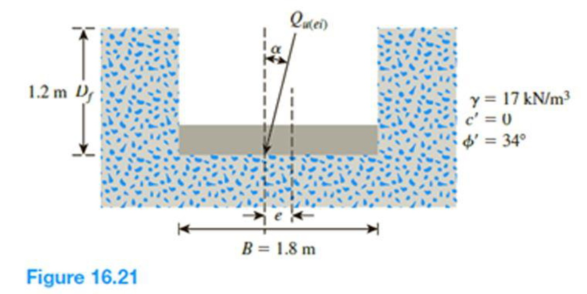
Figure 16.21 shows a continuous foundation with a width of 1.8 m constructed at a depth of 1.2 m in a granular soil. The footing is subjected to an eccentrically inclined loading with e = 0.3 m, and α = 10°. Determine the gross ultimate load, Qu(ei), that the footing can support using:
- a. Meyerhof (1963) method [Eq. (16.52)]
- b. Saran and Agarwal (1991) method [Eq. (16.53)]
- c. Patra et al. (2012) reduction factor method [Eq. (16.54)]
(a)
The gross ultimate load
Answer to Problem 16.19P
The gross ultimate load
Explanation of Solution
Given information:
The unit weight of the soil
The value of cohesion
The soil friction angle
The location of depth of footing base
The width of the footing B is 1.8 m.
The value of eccentricity e is 0.3 m.
The inclined angle
Calculation:
Determine the effective width of the footing using the relation.
Substitute 1.8 m for B and 0.3 for e.
For the continuous foundation, all shape factors are equal to one
Determine the depth factor
Substitute 1.2 m for
Determine the depth factor
Substitute
Determine the inclination factor
Substitute
Determine the inclination factor
Substitute
Determine the ultimate bearing capacity of the soil
Here,
Refer Table 16.2, “Bearing-capacity factors
For
The values of
Substitute 0 for
Determine the gross ultimate load
Substitute
Therefore, the gross ultimate load
(b)
The gross ultimate load
Answer to Problem 16.19P
The gross ultimate load
Explanation of Solution
Given information:
The unit weight of the soil
The value of cohesion
The soil friction angle
The location of depth of footing base
The width of the footing B is 1.8 m.
The value of eccentricity e is 0.3 m.
The inclined angle
Calculation:
Determine the ratio of
Substitute 0.3 for e and 1.8 m for B.
Determine the gross ultimate load
Here,
Refer Figure 16.14, “Variation of
Take the
Refer Figure 16.15, “Variation of
Take the
Refer Figure 16.16, “Variation of
Take the
Substitute 0 for
Therefore, the gross ultimate load
(c)
The gross ultimate load
Answer to Problem 16.19P
The gross ultimate load
Explanation of Solution
Given information:
The unit weight of the soil
The value of cohesion
The soil friction angle
The location of depth of footing base
The width of the footing B is 1.8 m.
The value of eccentricity e is 0.3 m.
The inclined angle
Calculation:
For the continuous foundation, all shape factors are equal to one
Determine the depth factor
Substitute 1.2 m for
Determine the depth factor
Substitute
Determine the ultimate bearing capacity of the soil
Refer Table 16.2, “Bearing-capacity factors
Take the
Substitute 0 for
Determine the gross ultimate load
Substitute 1.8 m for B,
Therefore, the gross ultimate load
Want to see more full solutions like this?
Chapter 16 Solutions
MindTap Engineering for Das/Sobhan's Principles of Geotechnical Engineering, SI Edition, 9th Edition, [Instant Access], 2 terms (12 months)


- Consider a continuous foundation of width B = 1.4 m on a sand deposit with c = 0, = 38, and = 17.5 kN/m3. The foundation is subjected to an eccentrically inclined load (see Figure 6.33). Given: load eccentricity e = 0.15 m, Df = 1 m, and load inclination = 18. Estimate the failure load Qu(ei) per unit length of the foundation a. for a partially compensated type of loading [Eq. (6.89)] b. for a reinforced type of loading [Eq. (6.90)]arrow_forwardQ1.1// The figure below shows the plan of a rectangular raft foundation which supports a total load of 40500 kN. The foundation is located at 3 m from the surface. Evaluate the increase in the effective stress at a point 8 m below the surface and having x, y coordinates as (-9, -6.5) with respect to the central axis of the footing. X 15 m w 6arrow_forwardA square shallow foundation (B × B) is planned to be constructed on a normality consolidated (NC) clay soil as shown in the below figure. The maximum acceptable settlement for the foundation is equal to 2.0 inches (5 cm), and the safety factor against bearing capacity is FS = 4. Determine the size of foundation. (Note: To simplify the calculations, ignore both the elastic settlement and secondary compression settlement. Also consider 4o'ave = 40'm) Q = 500 kN Ysat = 19.24 kN/m³ en = 0.8 C. = 0.25 p'= 0 c'= 25 kPa 2 m B ×B FS again Bearing Capacity = 4 Acceptable settlement = 2.0 inches 10 marrow_forward
- The shallow foundation shown below measures 2 m x 3 m and is subjected to a centric load and a moment. If eg = 0.2 m, ez = 0.3 m, and the depth of foundation is 1 m, determine the allowable load the foundation can carry. Use a factor of safety of 3. For the soil, we are told that the unit weight, y = 17 kn/m³, friction angle o' = 30°, and the cohesion, c' = 0. Qult B× L Qult eL Qult Qaln My Barrow_forwardA 10ft x 8ft foundation is set 4 feet below grade in the geotechnical setting provided in the above problem No 1, an applied load Q of 420kips is supported by this footing. Calculate the change of stress at 15ft and 30ft below grade at the center of the footing using: a. The 2:1 method b. m and n method The foundation is presented in problem above is subjected to a vertical force as noted and a single moment of 100 kip-ft perpendicular to 10ft face. Calculate: a. Ultimate bearing capacity using modified method b. Factor of safety in designarrow_forwardA long foundation 0.6 m wide carries a line load of 100 kN/m. Calculate the vertical stress σz, at a point P, the coordinates of which are x = 2.75 m, and z = 1.5 m, where the x-coordinate is normal to the line load from the central line of the footing.arrow_forward
- Q2: Compute the total stresses, which induced from geostatic stress and increase vertical stress from circular foundation under points A and B to 3 and 6 m depth from the base of the foundation. The foundation was constructed at 2.0 m below the natural ground level (NGL). The surface load intensity is 330 kN/m². R1= 4, (calculate R2 from the drawing, do not assume it). Assume any other parameter you need in your answer. Aqs netarrow_forwardA strip footing is to be designed to support a dead load of 500 kN/m and an imposed load of 300 kN/m at a depth of 0.7 m in a gravelly sand. Characteristic values of the shear strength parameters are c' = 0 and ϕ' =40˚. (a) Determine the required width of the footing if a factor of safety of 3.0 and assuming that the water table may rise to foundation level. (b) Would a foundation of that width satisfy the bearing resistance limit state? The unit weight of the sand above the water table is 17 kN/m3 and below the water table the saturated unit weight is 20 kN/m3.arrow_forwardA 4-m square footing is shown in figure B which supports a load Q = 5000 kN. In this problem H1 = 8 m and H2 = 12 m. Calculate: a. The pressure at the base of the footing b. The pressure at the mid height of the clay layer assuming that the stress beneath the footing is spread at a slope of 1H to 2V c. The pressure at the mid height of the clay layer [below the center of the footing using Bousinessq equation assuming point loadarrow_forward
- A rectangular footing has dimensions shown and is acted upon by a dead load of 570.00 kN and a live load of 621.00 kN. The column dimension is 366x576 mm where the shorter dimension is parallel to B. The thickness of the footing is 476mm. f'c=28 MPa and fy=420 MPa for diameter 20mm bars. A=2.5m and B=4.5m Calculate the ratio of the Ultimate Shear Force to Shear Capacity in two- way shear. Answer is 0.9238 (Complete Solution)arrow_forwardA rectangular footing 2.0 m x 2.5 m carries three columns at distances from the footing center as shown below. The column loads are: P₁ = 400 kN and P₂ = P3= 200 kN. For the soil profile and properties given, check the safety factor against bearing capacity failure. (Use yw = 10 kN/m³) 0.4 m 0.2 m 2 N Depth be w surface in meters 4 C. 3 (a TENT 7 8 Note: pictures are not drawn to sale 00 0.8 m B 0.8 m 3 Water table ROCK Soil surface WIT Sand c = 0 kPa, = 30° = 16 kN/m³ Y Ysat = 20 kN/m³ Es = 12 MPa, v = 0.3 Clay c = 60 kPa, = 0° Y = 14 kN/m³ Ysat = 19 kN/m³ Cc = 0.3, Cs = 0.1 eo = 1.0 P= 245 kPaarrow_forwardProblem.№₂3 - The plan of a mat foundation is shown in Figure. Calculate the soil pressure at points A, B, C, D, E, and F. (Note: All column sections are planned to be 0.5 m 3 0.5 m.) All loads shown are factored loads according to ACI 381-11 (2011). 550 KN 2000 KN 5.25 m 2000 KN 550 kN F *K 0.25 m G H 10 m ! B i 660 kN 2000 KN 10 m 2000 KN 660 kN E 600 KN 1600 KN 5.25 m 10 m 1600 KN 470 kN C D *K 0.25 m 9 m 9 m 9 m 0.25 m 0.25 marrow_forward
 Principles of Geotechnical Engineering (MindTap C...Civil EngineeringISBN:9781305970939Author:Braja M. Das, Khaled SobhanPublisher:Cengage Learning
 Principles of Foundation Engineering (MindTap Cou...Civil EngineeringISBN:9781337705028Author:Braja M. Das, Nagaratnam SivakuganPublisher:Cengage Learning
 Principles of Foundation Engineering (MindTap Cou...Civil EngineeringISBN:9781305081550Author:Braja M. DasPublisher:Cengage Learning
 Fundamentals of Geotechnical Engineering (MindTap...Civil EngineeringISBN:9781305635180Author:Braja M. Das, Nagaratnam SivakuganPublisher:Cengage Learning