FUNDAMENTALS OF ELEC.CIRC.(LL) >CUSTOM<
6th Edition
ISBN: 9781260503876
Author: Alexander
Publisher: MCG CUSTOM
bartleby

Videos

Textbook Question
Book Icon
Chapter 16, Problem 51P

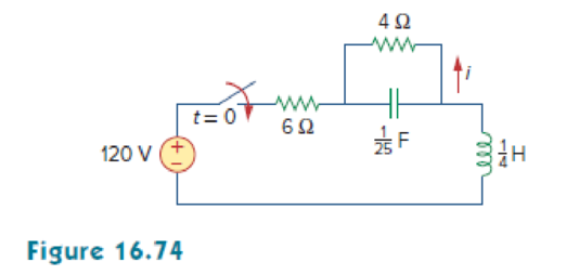
In the circuit of Fig. 16.74, find i(t) for t > 0.

Chapter 16, Problem 51P, In the circuit of Fig. 16.74, find i(t) for t  0.

Expert Solution & Answer
Check Mark
To determine

Find the expression of current i(t) for t>0 in the circuit of Figure 16.74.

Answer to Problem 51P

The expression of current i(t) for t>0 in the circuit of Figure 16.74 is [12+41.17e15.125tcos(4.608t73.06°)]u(t)A.

Explanation of Solution

Given data:

Refer to Figure 16.74 in the textbook.

Formula used:

Write a general expression to calculate the impedance of a resistor in s-domain.

ZR=R (1)

Here,

R is the value of resistance.

Write a general expression to calculate the impedance of an inductor in s-domain.

ZL=sL (2)

Here,

L is the value of inductance.

Write a general expression to calculate the impedance of a capacitor in s-domain.

ZC=1sC (3)

Here,

C is the value of capacitance.

Calculation:

The given circuit is redrawn as shown in Figure 1.

FUNDAMENTALS OF ELEC.CIRC.(LL) >CUSTOM<, Chapter 16, Problem 51P , additional homework tip  1

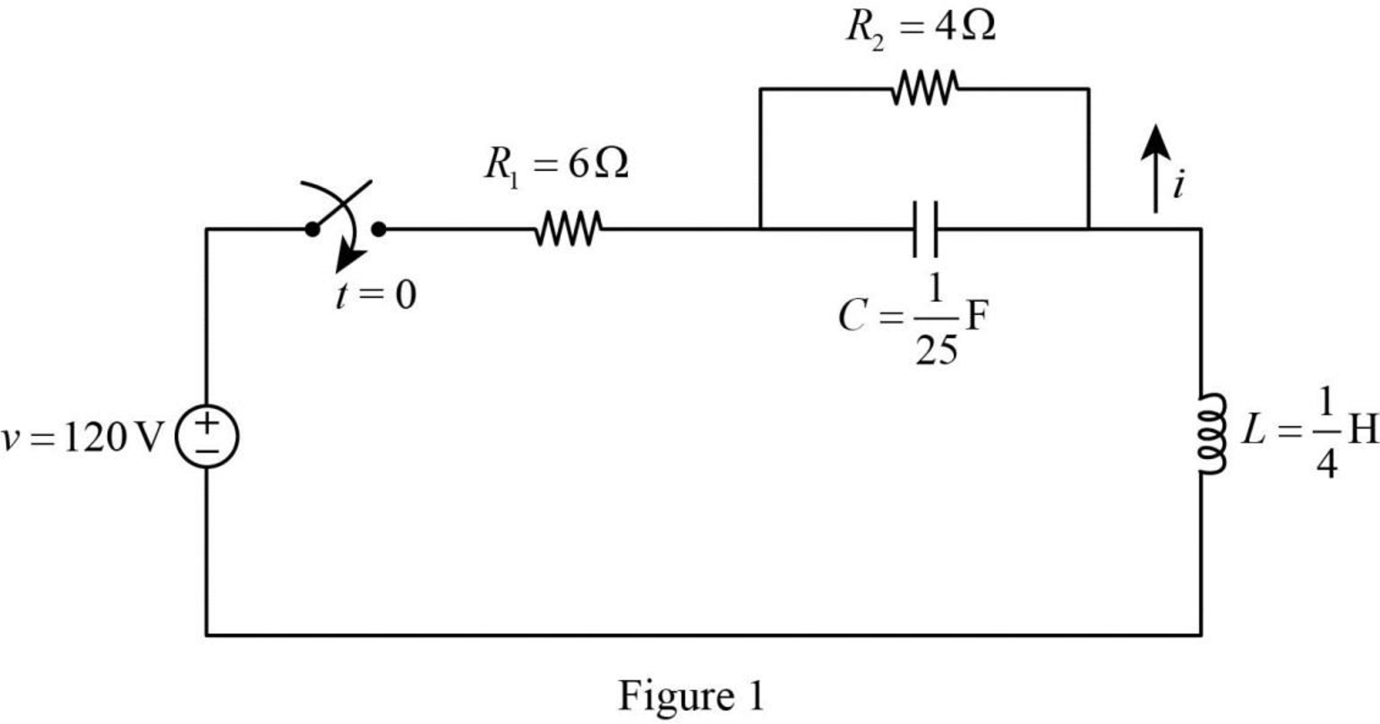
For a DC circuit, at steady state condition when time t=0 the capacitor acts like open circuit and the inductor acts like short circuit.

Now, the Figure 1 is reduced as shown in Figure 2.

FUNDAMENTALS OF ELEC.CIRC.(LL) >CUSTOM<, Chapter 16, Problem 51P , additional homework tip  2

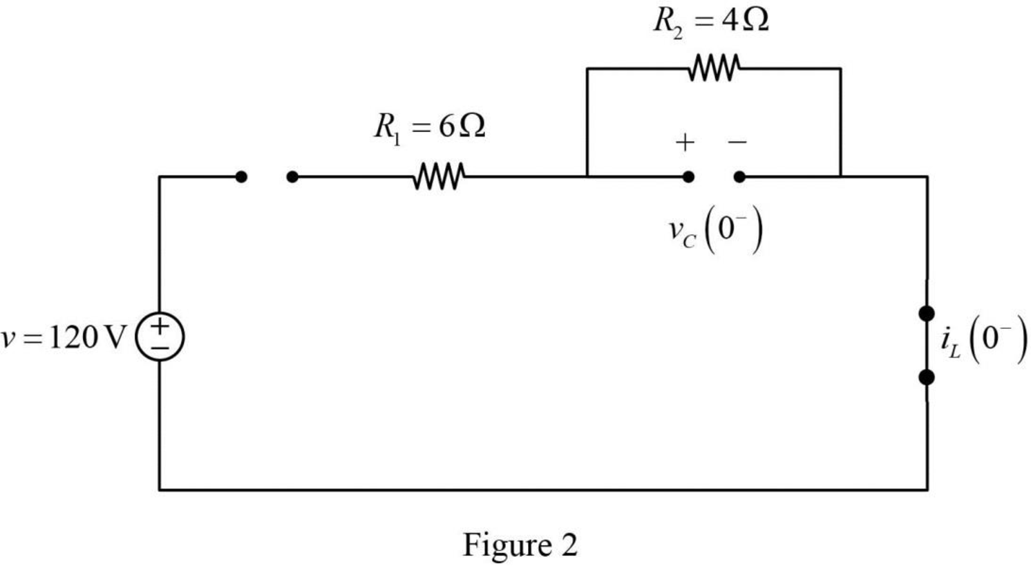
Refer to Figure 2, the switch is open and there is no source connected to the circuit. Therefore, the voltage across the capacitor and current through inductor are zero.

iL(0)=0AvC(0)=0V

The current through inductor and voltage across capacitor is always continuous so that,

i(0)=iL(0)=iL(0+)=0A

v(0)=vC(0)=vC(0+)=0V

For time t>0, the switch is closed and the Figure 1 is drawn as shown in Figure 3.

FUNDAMENTALS OF ELEC.CIRC.(LL) >CUSTOM<, Chapter 16, Problem 51P , additional homework tip  3

Substitute 6Ω for R1 in equation (1) to find ZR1.

ZR1=6Ω

Substitute 4Ω for R2 in equation (1) to find ZR2.

ZR2=4Ω

Substitute 14H for L in equation (2) to find ZL.

ZL=s(14H)=14s

Substitute 125F for C in equation (3) to find ZC.

ZC=1s(125F)=25s

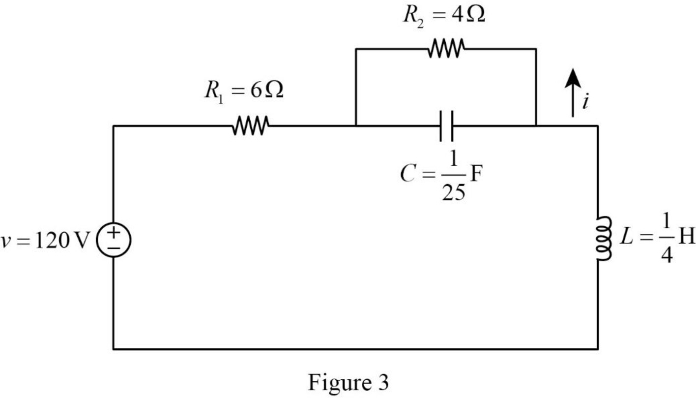
Refer to Figure 3, the circuit for t>0 is drawn. The source voltage v is also written as follows:

v=vs=120V=120(1)=120u(t)V{u(t)=1fort>0}

Apply Laplace transform for above to find Vs(s).

Vs(s)=120(1s){L(u(t))=1s}=120s

Convert the Figure 3 into s-domain.

FUNDAMENTALS OF ELEC.CIRC.(LL) >CUSTOM<, Chapter 16, Problem 51P , additional homework tip  4

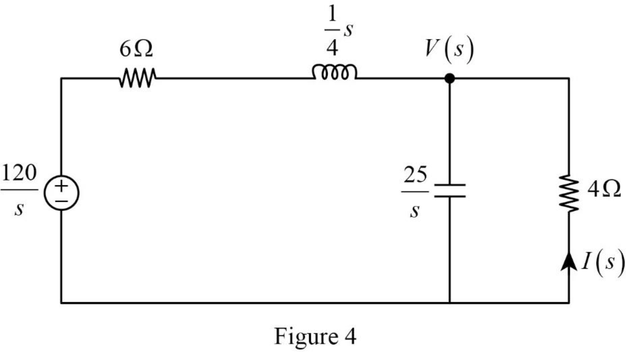
Apply nodal analysis at node V(s) in Figure 4.

V(s)120s6+14s+V(s)(25s)+V(s)4=0V(s)(6+14s)120s(6+14s)+V(s)(25s)+V(s)4=0V(s)(s+244)120s(s+244)+sV(s)25+V(s)4=04V(s)s+244(120)s(s+24)+sV(s)25+V(s)4=0

Simplify the above equation as follows:

4V(s)s+24+sV(s)25+V(s)4=480s(s+24)V(s)[4s+24+s25+14]=480s(s+24)V(s)[4(25)(4)+4s(s+24)+25(s+24)100(s+24)]=480s(s+24)V(s)[400+4s2+96s+25s+600100(s+24)]=480s(s+24)

Simplify the above equation as follows:

V(s)[4s2+121s+1000100(s+24)]=480s(s+24)V(s)[4(s2+30.25s+250)100(s+24)]=480s(s+24)V(s)[(s2+30.25s+250)25(s+24)]=480s(s+24)

Simplify the above equation to find V(s).

V(s)=480s(s+24)(25(s+24)s2+30.25s+250)

V(s)=12000s(s2+30.25s+250) (4)

From the above equation, the characteristic equation is

s2+30.25s+250=0 (5)

Write a general expression to calculate the roots of quadratic equation (as2+bs+c=0).

s1,2=b±b24ac2a (6)

Comparing equation (5) with the equation (as2+bs+c=0).

a=1b=30.25c=250

Substitute 1 for a, 30.25 for b, and 250 for c in equation (6) to find s1,2.

s1,2=30.25±(30.25)24(1)(250)2(1)=30.25±915.062510002(1)=30.25±84.93752=30.25±j9.2162

Simplify the above equation to find s1,2.

s1,2=30.25+j9.2162,30.25j9.2162=15.25+j4.608,15.25j4.608

Substitute the roots of characteristic equation in equation (4) to find V(s).

V(s)=12000s(s(15.125+j4.608))((s(15.125j4.608)))=12000s(s(15.125+j4.608))(s(15.125j4.608))

Take partial fraction for above equation.

V(s)=12000[s(s(15.125+j4.608))(s(15.125j4.608))]

V(s)=[As+B(s(15.125+j4.608))+C(s(15.125j4.608))] (7)

The equation (7) can also be written as follows:

12000[s(s(15.125+j4.608))(s(15.125j4.608))]=[A(s(15.125+j4.608))(s(15.125j4.608))+Bs(s(15.125j4.608))+Cs(s(15.125+j4.608))[s(s(15.125+j4.608))(s(15.125j4.608))]]

Simplify the above equation as follows:

12000=[A(s(15.125+j4.608))(s(15.125j4.608))+Bs(s(15.125j4.608))+Cs(s(15.125+j4.608))] . (8)

Substitute 0 for s in equation (8) to find A.

12000=[A(0(15.125+j4.608))(0(15.125j4.608))+B(0)(0(15.125j4.608))+C(0)(0(15.125+j4.608))]12000=[A((15.125+j4.608))((15.125j4.608))+0+0]12000=[A(15.125+j4.608)(15.125j4.608)]12000=A((15.125)2(j4.608)2){a2b2=(a+b)(ab)}

Simplify the above equation as follows:

12000=A(228.765j221.234)12000=A(228.765(1)21.234){j2=1}12000=A(228.765+21.234)12000=A(250)

Simplify the above equation to find A.

A=12000250=48

Substitute 15.125+j4.608 for s in equation (8) to find B.

12000=[A((15.125+j4.608)(15.125+j4.608))((15.125+j4.608)(15.125j4.608))+B(15.125+j4.608)((15.125+j4.608)(15.125j4.608))+C(15.125+j4.608)((15.125+j4.608)(15.125+j4.608))]12000=[A(0)+B(15.125+j4.608)(j9.216)+C(0)]12000=[0+B(15.125+j4.608)(j9.216)+0]

Simplify the above equation to find B.

B=12000(j9.216)(15.125+j4.608)=24+j78.7=82.35106.94°

Substitute 15.125j4.608 for s in equation (8) to find C.

12000=[A((15.125j4.608)(15.125+j4.608))((15.125j4.608)(15.125j4.608))+B(15.125j4.608)((15.125j4.608)(15.125j4.608))+C(15.125j4.608)((15.125j4.608)(15.125+j4.608))]12000=[A(0)+B(0)+C(15.125j4.608)(j9.216)]

Simplify the above equation to find C.

C=12000(j9.216)(15.125j4.608)=24j7.87=82.35106.94°

Substitute 48 for A, 82.35106.94° for B, and 82.35106.94° for C in equation (7) to find V(s).

V(s)=[48s+82.35106.94°(s(15.125+j4.608))+82.35106.94°(s(15.125j4.608))]

Refer to Figure 3, the current through resistor R2 is calculated as follows:

I(s)=V(s)4

Substitute [48s+82.35106.94°(s(15.125+j4.608))+82.35106.94°(s(15.125j4.608))] for V(s) in above equation to find I(s).

I(s)=[48s+82.35106.94°(s(15.125+j4.608))+82.35106.94°(s(15.125j4.608))](4)=[12s+20.58773.06°(s(15.125+j4.608))+20.58773.06°(s(15.125j4.608))]=[12s+20.587(cos(73.06°)+jsin(73.06°))(s(15.125+j4.608))+20.587(cos(73.06°)+jsin(73.06°))(s(15.125j4.608))]=[12s+20.587ej73.06°(s(15.125+j4.608))+20.587ej73.06°(s(15.125j4.608))]{eiθ=cosθ+isinθ}

Take inverse Laplace transform for above equation to find i(t).

i(t)=[12u(t)+20.587ej73.06°e(15.125+j4.608)tu(t)+20.587ej73.06°e(15.125j4.608)tu(t)]{L1(1sa)=eatu(t)}=[12+20.587e(15.125t+j4.608tj73.06°)+20.587e(15.125tj4.608t+j73.06°)]u(t){eaeb=ea+b}=[12+20.587e15.125tej4.608tj73.06°+20.587e15.125tej4.608t+j73.06°]u(t)=[12+20.587e15.125tej(4.608t73.06°)+20.587e15.125tej(4.608tj73.06°)]u(t)

Simplify the above equation to find i(t).

i(t)=[12+20.587e15.125t[ej(4.608t73.06°)+ej(4.608tj73.06°)]]u(t)=[12+20.587e15.125t[2cos(4.608t73.06°)]]u(t){cosθ=eiθ+eiθ2}=[12+41.17e15.125tcos(4.608t73.06°)]u(t)A

Conclusion:

Thus, the expression of current i(t) for t>0 in the circuit of Figure 16.74 is [12+41.17e15.125tcos(4.608t73.06°)]u(t)A.

Want to see more full solutions like this?

Subscribe now to access step-by-step solutions to millions of textbook problems written by subject matter experts!
Students have asked these similar questions
Explain the following: 1) LTI Systems2) Frequency response of LTI Systems 3) LTI System Eigen-function and Eigen-value
A system whose dynamic equations   dx(t)/dt = Ax(t) + Bu(t)      y(t) = Cx(t)   are given as . Find the eigenvalues ​​of A. Find the transfer relationship between X(s) and U(s). Find the Y (s)/ U(s) transfer function.
For a continuous time LTI system, the output is given as Y(s)=10(2s+3)/(s2+4s+5).  Find out the final value of y(t) using final value theorem.

Chapter 16 Solutions

FUNDAMENTALS OF ELEC.CIRC.(LL) >CUSTOM<

Ch. 16.5 - Prob. 11PPCh. 16.5 - Prob. 12PPCh. 16.6 - For what value of is the circuit in Fig. 16.29...Ch. 16.6 - Prob. 14PPCh. 16.6 - Prob. 15PPCh. 16.6 - Synthesize the function Vo(s)Vin=2ss2+6s+10 using...Ch. 16 - Prob. 1RQCh. 16 - The current through an RL series circuit with...Ch. 16 - Prob. 3RQCh. 16 - Prob. 4RQCh. 16 - Prob. 5RQCh. 16 - Prob. 6RQCh. 16 - Prob. 7RQCh. 16 - Prob. 8RQCh. 16 - Prob. 9RQCh. 16 - Prob. 10RQCh. 16 - The current in an RLC circuit is described by...Ch. 16 - The differential equation that describes the...Ch. 16 - Prob. 3PCh. 16 - If R = 20 , L = 0.6 H, what value of C will make...Ch. 16 - The responses of a series RLC circuit are vc(t) =...Ch. 16 - Prob. 6PCh. 16 - Prob. 7PCh. 16 - Prob. 8PCh. 16 - Prob. 9PCh. 16 - The step responses of a series RLC circuit are Vc...Ch. 16 - The step response of a parallel RLC circuit is v =...Ch. 16 - Prob. 12PCh. 16 - Prob. 13PCh. 16 - Prob. 14PCh. 16 - For the circuit in Fig. 16.38. calculate the value...Ch. 16 - The capacitor in the circuit of Fig. 16.39 is...Ch. 16 - If is(t) = 7.5e2t u(t) A in the circuit shown in...Ch. 16 - Find v(t), t 0 in the circuit of Fig. 16.41. Let...Ch. 16 - The switch in Fig. 16.42 moves from position A to...Ch. 16 - Find i(t) for t 0 in the circuit of Fig. 16.43.Ch. 16 - In the circuit of Fig. 16.44, the switch moves...Ch. 16 - Find the voltage across the capacitor as a...Ch. 16 - Obtain v (t) for t 0 in the circuit of Fig....Ch. 16 - The switch in the circuit of Fig. 16.47 has been...Ch. 16 - Calculate v(t) for t 0 in the circuit of Fig....Ch. 16 - Prob. 26PCh. 16 - Find v (t) for t 0 in the circuit in Fig. 16.50.Ch. 16 - For the circuit in Fig. 16.51, find v(t) for t 0.Ch. 16 - Prob. 29PCh. 16 - Find vo(t), for all t 0, in the circuit of Fig....Ch. 16 - Prob. 31PCh. 16 - For the network in Fig. 16.55, solve for i(t) for...Ch. 16 - Using Fig. 16.56, design a problem to help other...Ch. 16 - Prob. 34PCh. 16 - Prob. 35PCh. 16 - Prob. 36PCh. 16 - Prob. 37PCh. 16 - The switch in the circuit of Fig. 16.61 is moved...Ch. 16 - Prob. 39PCh. 16 - Prob. 40PCh. 16 - Prob. 41PCh. 16 - Prob. 42PCh. 16 - Prob. 43PCh. 16 - Prob. 44PCh. 16 - Find v(t) for t 0 in the circuit in Fig. 16.68.Ch. 16 - Prob. 46PCh. 16 - Determine io(t) in the network shown in Fig....Ch. 16 - Prob. 48PCh. 16 - Find i0(t) for t 0 in the circuit in Fig. 16.72....Ch. 16 - Prob. 50PCh. 16 - In the circuit of Fig. 16.74, find i(t) for t 0.Ch. 16 - Prob. 52PCh. 16 - In the circuit of Fig. 16.76, the switch has been...Ch. 16 - Prob. 54PCh. 16 - Prob. 55PCh. 16 - Calculate io(t) for t 0 in the network of Fig....Ch. 16 - Prob. 57PCh. 16 - Prob. 58PCh. 16 - Find vo(t) in the circuit of Fig. 16.82 if vx(0) =...Ch. 16 - Prob. 60PCh. 16 - Prob. 61PCh. 16 - Using Fig. 16.85, design a problem to help other...Ch. 16 - Consider the parallel RLC circuit of Fig. 16.86....Ch. 16 - The switch in Fig. 16.87 moves from position 1 to...Ch. 16 - For the RLC circuit shown in Fig. 16.88, find the...Ch. 16 - For the op amp circuit in Fig. 16.89, find v0(t)...Ch. 16 - Given the op amp circuit in Fig. 16.90, if v1(0+)...Ch. 16 - Prob. 68PCh. 16 - Prob. 69PCh. 16 - Using Fig. 16.93, design a problem to help other...Ch. 16 - Prob. 71PCh. 16 - The transfer function of a system is H(s)=s23s+1...Ch. 16 - Prob. 73PCh. 16 - Design a problem to help other students better...Ch. 16 - Prob. 75PCh. 16 - For the circuit in Fig. 16.95, find H(s) =...Ch. 16 - Obtain the transfer function H(s) = VoVs for the...Ch. 16 - Prob. 78PCh. 16 - For the circuit in Fig. 16.97, find: (a) I1/Vs (b)...Ch. 16 - Refer to the network in Fig. 16.98. Find the...Ch. 16 - Prob. 81PCh. 16 - Prob. 82PCh. 16 - Refer to the RL circuit in Fig. 16.101. Find: (a)...Ch. 16 - A parallel RL circuit has R = 4 and L = 1 H. The...Ch. 16 - Prob. 85PCh. 16 - Prob. 86PCh. 16 - Prob. 87PCh. 16 - Prob. 88PCh. 16 - Develop the state equations for the circuit shown...Ch. 16 - Prob. 90PCh. 16 - Prob. 91PCh. 16 - Prob. 92PCh. 16 - Prob. 93PCh. 16 - Prob. 94PCh. 16 - Prob. 95PCh. 16 - Prob. 96PCh. 16 - A system is formed by cascading two systems as...Ch. 16 - Determine whether the op amp circuit in Fig....Ch. 16 - It is desired realize the transfer function...Ch. 16 - Prob. 100PCh. 16 - Prob. 101PCh. 16 - Synthesize the transfer function...Ch. 16 - Prob. 103CPCh. 16 - Prob. 104CPCh. 16 - Prob. 105CP
Knowledge Booster
Background pattern image
Electrical Engineering
Learn more about
Need a deep-dive on the concept behind this application? Look no further. Learn more about this topic, electrical-engineering and related others by exploring similar questions and additional content below.
Similar questions
SEE MORE QUESTIONS
Recommended textbooks for you
Text book image
Introductory Circuit Analysis (13th Edition)
Electrical Engineering
ISBN:9780133923605
Author:Robert L. Boylestad
Publisher:PEARSON
Text book image
Delmar's Standard Textbook Of Electricity
Electrical Engineering
ISBN:9781337900348
Author:Stephen L. Herman
Publisher:Cengage Learning
Text book image
Programmable Logic Controllers
Electrical Engineering
ISBN:9780073373843
Author:Frank D. Petruzella
Publisher:McGraw-Hill Education
Text book image
Fundamentals of Electric Circuits
Electrical Engineering
ISBN:9780078028229
Author:Charles K Alexander, Matthew Sadiku
Publisher:McGraw-Hill Education
Text book image
Electric Circuits. (11th Edition)
Electrical Engineering
ISBN:9780134746968
Author:James W. Nilsson, Susan Riedel
Publisher:PEARSON
Text book image
Engineering Electromagnetics
Electrical Engineering
ISBN:9780078028151
Author:Hayt, William H. (william Hart), Jr, BUCK, John A.
Publisher:Mcgraw-hill Education,
Systems and Simulation - Lecture 3: Modelling of Mechanical systems; Author: bioMechatronics Lab;https://www.youtube.com/watch?v=fMcDdyoC9mA;License: Standard Youtube License