
FUNDAMENTALS OF ELEC.CIRC.(LL) >CUSTOM<
6th Edition
ISBN: 9781260503876
Author: Alexander
Publisher: MCG CUSTOM
expand_more
expand_more
format_list_bulleted
Videos
Textbook Question
Chapter 16, Problem 97P
A system is formed by cascading two systems as shown in Fig. 16.106. Given that the impulse responses of the systems are
- (a) Obtain the impulse response of the overall system.
- (b) Check if the overall system is stable.
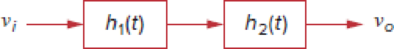
Figure 16.106
Expert Solution & Answer
Want to see the full answer?
Check out a sample textbook solution
Students have asked these similar questions
R
For the RL circuit, find the mathematical model (input-output relationship) if the output is the inductor voltage, VL(t)=y(t) and R=13 0, L=5 H.
O a. x'(t) = y'(t)+2,60y'(t)
O b. x'(t) = y'(t)+ 2,60y(t)
O c x(t) = y(t)'+ 0,38y(t)
O d. x(t) = y(t)+ 2,60y'(t)
O e. x'(t) = y'(t)+ 0,38y(t)
O f. x(t) = y(t)+ 0,38y'(t)
O g. x(t) = y(t)+ 0,38y(t)
O h. x'(t) = y(t)+ 2,60y(t)
16.30 Find v (1), for all > 0, in the circuit of Fig. 16.53.
152
1592
7u(t) V
Figure 16.53
For Prob. 16.30.
1H
0.5 Fo
3.5u(t) A
X
R
For the RL circuit, find the mathematical model (input-output relationship) if the output is the inductor voltage, V₁(t)=y(t) and R=17 Q2, L=5 H.
(Watch out for the derivative symbol!)
Chapter 16 Solutions
FUNDAMENTALS OF ELEC.CIRC.(LL) >CUSTOM<
Ch. 16.2 - Determine vo(t) in the circuit of Fig. 16.6,...Ch. 16.2 - Prob. 2PPCh. 16.2 - Prob. 3PPCh. 16.3 - For the circuit shown in Fig. 16.12 with the same...Ch. 16.3 - Prob. 5PPCh. 16.3 - The initial energy in the circuit of Fig. 16.17 is...Ch. 16.4 - Prob. 7PPCh. 16.4 - Prob. 8PPCh. 16.4 - Prob. 9PPCh. 16.5 - Obtain the state variable model for the circuit...
Ch. 16.5 - Prob. 11PPCh. 16.5 - Prob. 12PPCh. 16.6 - For what value of is the circuit in Fig. 16.29...Ch. 16.6 - Prob. 14PPCh. 16.6 - Prob. 15PPCh. 16.6 - Synthesize the function Vo(s)Vin=2ss2+6s+10 using...Ch. 16 - Prob. 1RQCh. 16 - The current through an RL series circuit with...Ch. 16 - Prob. 3RQCh. 16 - Prob. 4RQCh. 16 - Prob. 5RQCh. 16 - Prob. 6RQCh. 16 - Prob. 7RQCh. 16 - Prob. 8RQCh. 16 - Prob. 9RQCh. 16 - Prob. 10RQCh. 16 - The current in an RLC circuit is described by...Ch. 16 - The differential equation that describes the...Ch. 16 - Prob. 3PCh. 16 - If R = 20 , L = 0.6 H, what value of C will make...Ch. 16 - The responses of a series RLC circuit are vc(t) =...Ch. 16 - Prob. 6PCh. 16 - Prob. 7PCh. 16 - Prob. 8PCh. 16 - Prob. 9PCh. 16 - The step responses of a series RLC circuit are Vc...Ch. 16 - The step response of a parallel RLC circuit is v =...Ch. 16 - Prob. 12PCh. 16 - Prob. 13PCh. 16 - Prob. 14PCh. 16 - For the circuit in Fig. 16.38. calculate the value...Ch. 16 - The capacitor in the circuit of Fig. 16.39 is...Ch. 16 - If is(t) = 7.5e2t u(t) A in the circuit shown in...Ch. 16 - Find v(t), t 0 in the circuit of Fig. 16.41. Let...Ch. 16 - The switch in Fig. 16.42 moves from position A to...Ch. 16 - Find i(t) for t 0 in the circuit of Fig. 16.43.Ch. 16 - In the circuit of Fig. 16.44, the switch moves...Ch. 16 - Find the voltage across the capacitor as a...Ch. 16 - Obtain v (t) for t 0 in the circuit of Fig....Ch. 16 - The switch in the circuit of Fig. 16.47 has been...Ch. 16 - Calculate v(t) for t 0 in the circuit of Fig....Ch. 16 - Prob. 26PCh. 16 - Find v (t) for t 0 in the circuit in Fig. 16.50.Ch. 16 - For the circuit in Fig. 16.51, find v(t) for t 0.Ch. 16 - Prob. 29PCh. 16 - Find vo(t), for all t 0, in the circuit of Fig....Ch. 16 - Prob. 31PCh. 16 - For the network in Fig. 16.55, solve for i(t) for...Ch. 16 - Using Fig. 16.56, design a problem to help other...Ch. 16 - Prob. 34PCh. 16 - Prob. 35PCh. 16 - Prob. 36PCh. 16 - Prob. 37PCh. 16 - The switch in the circuit of Fig. 16.61 is moved...Ch. 16 - Prob. 39PCh. 16 - Prob. 40PCh. 16 - Prob. 41PCh. 16 - Prob. 42PCh. 16 - Prob. 43PCh. 16 - Prob. 44PCh. 16 - Find v(t) for t 0 in the circuit in Fig. 16.68.Ch. 16 - Prob. 46PCh. 16 - Determine io(t) in the network shown in Fig....Ch. 16 - Prob. 48PCh. 16 - Find i0(t) for t 0 in the circuit in Fig. 16.72....Ch. 16 - Prob. 50PCh. 16 - In the circuit of Fig. 16.74, find i(t) for t 0.Ch. 16 - Prob. 52PCh. 16 - In the circuit of Fig. 16.76, the switch has been...Ch. 16 - Prob. 54PCh. 16 - Prob. 55PCh. 16 - Calculate io(t) for t 0 in the network of Fig....Ch. 16 - Prob. 57PCh. 16 - Prob. 58PCh. 16 - Find vo(t) in the circuit of Fig. 16.82 if vx(0) =...Ch. 16 - Prob. 60PCh. 16 - Prob. 61PCh. 16 - Using Fig. 16.85, design a problem to help other...Ch. 16 - Consider the parallel RLC circuit of Fig. 16.86....Ch. 16 - The switch in Fig. 16.87 moves from position 1 to...Ch. 16 - For the RLC circuit shown in Fig. 16.88, find the...Ch. 16 - For the op amp circuit in Fig. 16.89, find v0(t)...Ch. 16 - Given the op amp circuit in Fig. 16.90, if v1(0+)...Ch. 16 - Prob. 68PCh. 16 - Prob. 69PCh. 16 - Using Fig. 16.93, design a problem to help other...Ch. 16 - Prob. 71PCh. 16 - The transfer function of a system is H(s)=s23s+1...Ch. 16 - Prob. 73PCh. 16 - Design a problem to help other students better...Ch. 16 - Prob. 75PCh. 16 - For the circuit in Fig. 16.95, find H(s) =...Ch. 16 - Obtain the transfer function H(s) = VoVs for the...Ch. 16 - Prob. 78PCh. 16 - For the circuit in Fig. 16.97, find: (a) I1/Vs (b)...Ch. 16 - Refer to the network in Fig. 16.98. Find the...Ch. 16 - Prob. 81PCh. 16 - Prob. 82PCh. 16 - Refer to the RL circuit in Fig. 16.101. Find: (a)...Ch. 16 - A parallel RL circuit has R = 4 and L = 1 H. The...Ch. 16 - Prob. 85PCh. 16 - Prob. 86PCh. 16 - Prob. 87PCh. 16 - Prob. 88PCh. 16 - Develop the state equations for the circuit shown...Ch. 16 - Prob. 90PCh. 16 - Prob. 91PCh. 16 - Prob. 92PCh. 16 - Prob. 93PCh. 16 - Prob. 94PCh. 16 - Prob. 95PCh. 16 - Prob. 96PCh. 16 - A system is formed by cascading two systems as...Ch. 16 - Determine whether the op amp circuit in Fig....Ch. 16 - It is desired realize the transfer function...Ch. 16 - Prob. 100PCh. 16 - Prob. 101PCh. 16 - Synthesize the transfer function...Ch. 16 - Prob. 103CPCh. 16 - Prob. 104CPCh. 16 - Prob. 105CP
Knowledge Booster


Learn more about
Need a deep-dive on the concept behind this application? Look no further. Learn more about this topic, electrical-engineering and related others by exploring similar questions and additional content below.Similar questions
- 5 Write the differential equation that is mathematically equivalent to the block diagram shown. Assume that r(t) = t^3 R(s) 54 +35³ +25² + s +1 55+ 454 +35³ +25² +35+2 C(s)arrow_forwardThe block diagram of a time-invariant, linear, continuous-time system is given below. X 1 (s) and X 2 (s) are the state variables of the system. U(s) is the input signal of the system, Y(s) is the output signal of the system . X7(S) 1 S+5 Y(S) U(S) S-2 X2(S) Transfer function of the system A s + Bs + C Y (s) G (s) = U (s) %3D D s + Es + F According to the form of C. What is the value of the parameter? Note : Write only the numerical value of the parameter. 3.arrow_forward+ X R For the RL circuit, find the mathematical model (input-output relationship) if the output is the inductor voltage, V₁₁ (t)=y(t) and R=15 02, L=3 H. (Watch out for the derivative symbol !) O a. x'(t) = y'(t)+ 5.00y(t) ○ b. x'(t) = y'(t)+ 5.00y'(t) O c. x'(t) = y(t)+ 5.00y(t) D. x'(t) = y'(t)+ 0.20y(t) to. x(t) = y(t)+ 0.20y'(t) O f. x(t) = y(t)+ 0.20y(t) O g. x(t) = y'(t)+ 0.20y(t) ○ h. x(t) = y(t)+ 5.00y'(t) ||| O Larrow_forward
- Find vo(t) in the circuit of Fig. 16.54 if vx(0) = 2 V and i(0) = 1 A. +Vx- i 1 F + ¹u(t) A (1 16.54 1Ω 19 1 H Voarrow_forwardThe mathematical model of a system is 2y" (t) + 3y' (t) + 3y(t) are y(0) = 2 and y'(0) = 3. Find the system output when the input is r(t) = u(t). lz' (t) + 1z(t) and the initial conditionsarrow_forwardFind the D.E of the system below, given that r(t) = +² et 4 (t), where u (+) is a step function. R (s) s² - +1 55+354 +25² +1 c(s)arrow_forward
- 16.20 Find i(t) for t> 0 in the circuit of Fig. 16.43. 36 V (+ Figure 16.43 For Prob. 16.20. 10 92 M t = 0 * 40 S2 60 92 li(t) 1 mF 2.5 Harrow_forward16.30 Find v(t), for all t > 0, in the circuit of Fig. 16.53. + 7u(t) V (+ ) 3.5u(t) A 1H 0.5 Farrow_forwardLet Y(s) be the unit-step response of a causal system, having a transfer function 3-S G(s) = (s+ 1)(s+ 3) that is, Y(s) = G(s) The forced response of the system is (a) u(t) (b) 2u(t) (c) u(t) - 2e'u(t) + e 3tu(t) (d) 2u(t) - 2eu(t) + e 3tu(t)arrow_forward
- + X R For the RL circuit, find the mathematical model (input-output relationship) if the output is the resistor voltage, VŔ(t)=y(t) and R=9 02, L=14 H. (Watch out for the derivative symbol!) O a. x(t) = y(t) + 1,56y'(t) O b. x(t) = y(t) + 1,56y(t) O c. x(t) = y(t) + 1,56y(t) O d. x(t) = y(t)+ 0,64y'(t) O e. x' (t) = y'(t) + 0,64y(t) O f. x'(t) = y'(t) + 0,64y'(t) O g. x'(t) = y(t) + 0,64y(t) Oh. x'(t) = y'(t) + 1,56y(t)arrow_forwardLet Y(s) be the unit-step response of a causal system, having a transfer function 3-s (s + 1)(S+ 3) that is, Y(s) = G(s) S G(s) = The forced response of the system is (b) 2u(t) (d) 2u(t) - 2e-¹u(t) + e-³tu(t) (a) u(t) (c) u(t) - 2e¹u(t) + e-³tu(t)arrow_forward3. Obtain the Differential Equation of the given system R(S) 54 +35³ +25² + s +1 55+ 484 +35³ +25² +38 +2 C(s)arrow_forward
arrow_back_ios
SEE MORE QUESTIONS
arrow_forward_ios
Recommended textbooks for you
 Introductory Circuit Analysis (13th Edition)Electrical EngineeringISBN:9780133923605Author:Robert L. BoylestadPublisher:PEARSON
 Delmar's Standard Textbook Of ElectricityElectrical EngineeringISBN:9781337900348Author:Stephen L. HermanPublisher:Cengage Learning
 Programmable Logic ControllersElectrical EngineeringISBN:9780073373843Author:Frank D. PetruzellaPublisher:McGraw-Hill Education
 Fundamentals of Electric CircuitsElectrical EngineeringISBN:9780078028229Author:Charles K Alexander, Matthew SadikuPublisher:McGraw-Hill Education
 Electric Circuits. (11th Edition)Electrical EngineeringISBN:9780134746968Author:James W. Nilsson, Susan RiedelPublisher:PEARSON
 Engineering ElectromagneticsElectrical EngineeringISBN:9780078028151Author:Hayt, William H. (william Hart), Jr, BUCK, John A.Publisher:Mcgraw-hill Education,
Introductory Circuit Analysis (13th Edition)
Electrical Engineering
ISBN:9780133923605
Author:Robert L. Boylestad
Publisher:PEARSON
Delmar's Standard Textbook Of Electricity
Electrical Engineering
ISBN:9781337900348
Author:Stephen L. Herman
Publisher:Cengage Learning
Programmable Logic Controllers
Electrical Engineering
ISBN:9780073373843
Author:Frank D. Petruzella
Publisher:McGraw-Hill Education
Fundamentals of Electric Circuits
Electrical Engineering
ISBN:9780078028229
Author:Charles K Alexander, Matthew Sadiku
Publisher:McGraw-Hill Education
Electric Circuits. (11th Edition)
Electrical Engineering
ISBN:9780134746968
Author:James W. Nilsson, Susan Riedel
Publisher:PEARSON
Engineering Electromagnetics
Electrical Engineering
ISBN:9780078028151
Author:Hayt, William H. (william Hart), Jr, BUCK, John A.
Publisher:Mcgraw-hill Education,
Types of Systems; Author: Neso Academy;https://www.youtube.com/watch?v=IRdDcSO_fQw;License: Standard youtube license