Concept explainers
Videos
Disk A has a mass mA = 4 kg, a radius rA = 300 mm, and an initial angular velocity ω0 = 300 rpm clockwise. Disk B has a mass mB = 1.6 kg, a radius rB = 180 mm, and is at rest when it is brought into contact with disk A. Knowing that μk = 0.35 between the disks and neglecting bearing friction, determine (a) the angular acceleration of each disk, (b) the reaction at the support C.
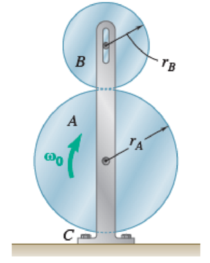
Fig. P16.43 and P16.44
(a)
Find the angular acceleration of each disk
Answer to Problem 16.43P
The angular acceleration of each disk
Explanation of Solution
The mass of the disk A
The mass of the disk B
The initial angular velocity of the disk A
The coefficient of the kinetic friction
The radius of the disk A
The radius of the disk B
Calculation:
Consider the acceleration due to gravity (g) as
Convert the unit of the radius of the disk A
Convert the unit of the radius of the disk B
Calculate the mass moment of inertia of the disk A
Substitute
Calculate the mass moment of inertia of the disk B
Substitute
Calculate the load of the disk A
Substitute
Calculate the load of the disk B
Substitute
Show the free body diagram of the disk B as in Figure 1.
Here,
Refer to Figure 1.
Calculate the vertical forces by applying the equation of equilibrium:
Sum of vertical forces is equal to 0.
Substitute
Calculate the magnitude of the friction force
Substitute
Calculate the horizontal forces by applying the equation of equilibrium:
Sum of horizontal forces is equal to 0.
Substitute
Calculate the angular acceleration of the disk B
Calculate the moment about point B by applying the equation of equilibrium:
Substitute
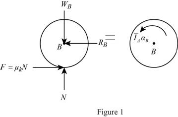
Show the free body diagram of the disk A as in Figure 2.
Here,
Refer to Figure 2.
Calculate the horizontal forces by applying the equation of equilibrium:
Sum of horizontal forces is equal to 0.
Substitute
Calculate the vertical forces by applying the equation of equilibrium:
Sum of vertical forces is equal to 0.
Substitute
Calculate the angular acceleration of the disk A
Calculate the moment about point A by applying the equation of equilibrium:
Substitute
Hence, the angular acceleration of each disk
(b)
Find the reaction at the support C
Answer to Problem 16.43P
The reaction at the support C
Explanation of Solution
The mass of the disk A
The mass of the disk B
The initial angular velocity of the disk A
The coefficient of the kinetic friction
The radius of the disk A
The radius of the disk B
Calculation:
Refer to part (a).
Show the free body diagram of the support C as in Figure 3.
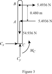
Here,
Refer to Figure 3.
Calculate the horizontal forces by applying the equation of equilibrium:
Sum of horizontal forces is equal to 0.
Calculate the vertical forces by applying the equation of equilibrium:
Sum of vertical forces is equal to 0.
Calculate the moment about point C by applying the equation of equilibrium:
Sum of moments about point C is equal to 0.
Substitute
Calculate the time required for the disk to come to rest (t):
Substitute
Calculate the final angular velocity of the disk A
Substitute
Calculate the final angular velocity of the disk B
Substitute
Hence, the reaction at the support C
Want to see more full solutions like this?
Chapter 16 Solutions
Connect 2 Semester Access Card for Vector Mechanics for Engineers: Statics and Dynamics
Additional Engineering Textbook Solutions
Engineering Mechanics: Statics & Dynamics (14th Edition)
Vector Mechanics for Engineers: Statics
Mechanics of Materials, 7th Edition
Vector Mechanics for Engineers: Statics, 11th Edition
Degarmo's Materials And Processes In Manufacturing
DeGarmo's Materials and Processes in Manufacturing


- The 30-kg reel is mounted on a 20 kg cart. The reel is free to rotate about the axle O. The radius of gyration, kO, about the mass center, O, is 250 mm and a cable is wrapped around the inner hub of the wheel. The mass of the wheels on the cart and the mass of the cable may be neglected. The system is at rest when a force, P, of 50 N is applied to the end of the cable. a) Determine the velocity of the cart after 4 seconds m/s b) determine the angular velocity of the reel, in rad/s. [Correct answers are a) 4.0 m/s b) 16 rad/sarrow_forwardThe uniform 4-kg cylinder A with a radius of r = 150 mm has an angular velocity of w0 = 50 rad/s when it is brought into contact with an identical cylinder B that is at rest. The coefficient of kinetic friction at the contact point D is μk. After a period of slipping, the cylinders attain constant angular velocities of equal magnitude and opposite direction at the same time. Knowing that cylinder A executes three revolutions before it attains a constant angular velocity and cylinder B executes one revolution before it attains a constant angular velocity, determine (a) the final angular velocity of each cylinder, (b) the coefficient of kinetic friction μk.arrow_forwardTwo uniform cylinders, each of mass m = 6 kg and radius r = 125 mm, are connected by a belt as shown. If the system is released from rest when t = 0, determine (a ) the velocity of the center of cylinder B at t=3s, ( b) the tension in the portion of belt connecting the two cylinders.arrow_forward
- Two uniform cylinders, each of weight W = 14 lb and radius r = 5 in., are connected by a belt as shown. If the system is released from rest, determine (a ) the velocity of the center of cylinder A after it has moved through 3 ft, (b) the tension in the portion of belt connecting the two cylinders.arrow_forwardA 5-m-long ladder has a mass of 15 kg and is placed against a house at an angle 0 = 20°. Knowing that the ladder is released from rest, determine the angular velocity of the ladder and the velocity of end A when 0 = 45°. Assume the ladder can slide freely on the horizontal ground and on the vertical wall.arrow_forwardDisk A, of weight 5 lb and radius r = 3 in., is at rest when it is placed in contact with a belt that moves at a constant speed v = 50 ft/s. Knowing that μk = 0.20 between the disk and the belt, determine the time required for the disk to reach a constant angular velocity.arrow_forward
- A slender 9-lb rod can rotate in a vertical plane about a pivot at B. A spring of constant k = 30 lb/ft and of unstretched length 6 in. is attached to the rod as shown. Knowing that the rod is released from rest in the position shown, determine its angular velocity after it has rotated through 90°.arrow_forwardTwo identical giant flywheels are on 2 identical slopes at an angle alpha = 20 deg. One flywheel is rolling on its inside shaft of diameter d1 = 3 ft, and the second flywheel is rolling without slipping on its outside diameter d2 = 5 ft. They are both released from rest. The weight of the flywheel is W = 8 lbs Knowing that flywheel 1 attains a speed of v = 7.0 ft/s in t = [t] s, (if t doesn't show take any t between 5 and 10 sec) find the radius of gyration of the flywheels, following those steps: b. Find omega final c. Find the angular impulse at the point of contact between the shaft and the slope. d. Write the formula to find the final momentum. e. Solve for k, using the principle of angular impulse and momentumarrow_forwardThe 30-kg uniform disk A and the bar BC are at rest and the 5-kg uniform disk D has an initial angular velocity of w1 with a magnitude of 440 rpm when the compressed spring is released and disk D contacts disk contacts disk A. The system rotates freely about the vertical spindle BE. After a period of slippage, disk D rolls without slipping. Knowing that the magnitude of the final angular velocity of disk D is 176 rpm, determine the final angular velocities of bar BC and disk A. Neglect the mass of bar BC.arrow_forward
- A drum A, of mass 200 kg, external diameter 380 mm and radius of gyration 150 mm, rotates on frictionless bearings at 250 rev/min. A stationary drum, B, of mass 50 kg, external diameter 200 mm and radius of gyration 80 mm, mounted on a frictionless axis parallel to that of A, is pressed into contact with A with a force of 90 N. The coefficient of friction is 0·25. Determine: The final speeds of A and B. (b) The time of slipping. (c) The time of slipping if a torque is applied to A, to maintain the speed of A as a constant 250 rev/min.arrow_forwardA 48-kg advertising panel of length 2a = 2.4 m and width 2b = 1.6 m is kept rotating at a constant rate w1 about its horizontal axis by a small electric motor attached at A to frame ACB. This frame itself is kept rotating at a constant rate w2 about a vertical axis by a second motor attached at C to the column CD. Knowing that the panel and the frame complete a full revolution in 6 s and 12 s, respectively, express, as a function of the angle 0, the dynamic reaction exerted on column CD by its support at D.arrow_forwardA 1.6-kg tube AB can slide freely on rod DE which in turn can rotate freely in a horizontal plane. Initially the assembly is rotating with an angular velocity of magnitude w = 5 rad/s and the tube is held in position by a cord. The moment of inertia of the rod and bracket about the vertical axis of rotation is 0.30 kg.m2 and the centroidal moment of inertia of the tube about a vertical axis is 0.0025 kg.m2If the cord suddenly breaks, determine (a) the angular velocity of the assembly after the tube has moved to end E, (b) the energy lost during the plastic impact at E.arrow_forward
 Elements Of ElectromagneticsMechanical EngineeringISBN:9780190698614Author:Sadiku, Matthew N. O.Publisher:Oxford University Press
 Mechanics of Materials (10th Edition)Mechanical EngineeringISBN:9780134319650Author:Russell C. HibbelerPublisher:PEARSON
 Thermodynamics: An Engineering ApproachMechanical EngineeringISBN:9781259822674Author:Yunus A. Cengel Dr., Michael A. BolesPublisher:McGraw-Hill Education
 Control Systems EngineeringMechanical EngineeringISBN:9781118170519Author:Norman S. NisePublisher:WILEY
 Mechanics of Materials (MindTap Course List)Mechanical EngineeringISBN:9781337093347Author:Barry J. Goodno, James M. GerePublisher:Cengage Learning
 Engineering Mechanics: StaticsMechanical EngineeringISBN:9781118807330Author:James L. Meriam, L. G. Kraige, J. N. BoltonPublisher:WILEY