
Videos
The hatchback of a car is positioned as shown to help determine the appropriate size for a damping
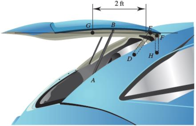
(a)
(b)
Fig. P16.134
(a)
The initial angular acceleration of the door.
Answer to Problem 16.134P
The initial angular acceleration of the door is
Explanation of Solution
Given information:
The weight of the door is
The mass moment of inertia of the center of gravity is
Calculation:
Consider the acceleration due to gravity as
Calculate the mass
Substitute
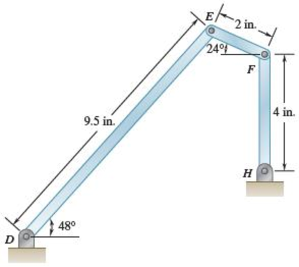
Sketch the Free Body Diagram of the door as shown in Figure 1.
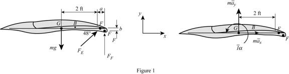
Refer to Figure 1.
Calculate the distance
Calculate the distance
Calculate the position vectors as shown below.
The position of F with respect to H.
The position of E with respect to F.
Substitute
The position of E with respect to D.
The position of G with respect to E.
Apply the Equations of Equilibrium as shown below.
Apply the Equilibrium of forces along x direction as shown below.
Substitute
Apply the Equilibrium of forces along y direction as shown below.
Substitute
Substitute
Apply the Equilibrium of moment about G as shown below.
Calculate the acceleration at F
Substitute
Calculate the acceleration at E
Substitute
Calculate the acceleration at E
Substitute
Equating Equations (4) and (5) as shown below.
Resolving i and j components as shown below.
For i component.
For j component.
Calculate the relative acceleration
Substitute
Resolving i and j components as shown below.
For i component.
For j component.
Calculate the force at F
Substitute
Substitute
Calculate the force at E
Substitute
Substitute
Calculate the angular acceleration
Substitute
Therefore, the initial angular acceleration of the door is
(b)
The force on link FH.
Answer to Problem 16.134P
The force on link FH is
Explanation of Solution
Given information:
The weight of the door is
The mass moment of inertia of the center of gravity is
Calculation:
Refer to part (a).
The initial angular acceleration of the door is
Calculate the force at F
Substitute
Therefore, the force on link FH is
Want to see more full solutions like this?
Chapter 16 Solutions
Connect 1 Semester Access Card for Vector Mechanics for Engineers: Statics and Dynamics
Additional Engineering Textbook Solutions
Automotive Technology: Principles, Diagnosis, and Service (5th Edition)
Automotive Technology: Principles, Diagnosis, And Service (6th Edition) (halderman Automotive Series)
Introduction To Finite Element Analysis And Design
Fundamentals of Aerodynamics
Heat and Mass Transfer: Fundamentals and Applications
Engineering Mechanics: Dynamics (14th Edition)


- 2. Determine the number of degrees of freedom necessary for the analysis of the system shown in the figure below. 0.1L 0.4L+ 0.3LS-+ 0.2L 2k G 2k Slender rod of mass m m2 moment of inertia Iarrow_forward5. Car doors are easy to slam shut but difficult to press shut by hand force. The door lock as two latches, the first easily engaged, and the second requiring the rubber seal around the door to be quite compressed before it can engage. The rubber seal gives a spring constant of 50,000N/m at the lock position for the door, and the mass moment of inertia for the door around its hinges is 2.5kg- m². The distance between the lock and the hinges is Im. Calculate what force is needed to press the car door shut at the lock if a speed of 0.8m/s at the lock slams it shut.arrow_forward1. Determine the number of degrees of freedom necessary for the analysis of the system shown in the figure below. Identical slender rods of length L and mass m 4.arrow_forward
- An inside cylinder locomotive has its cylinder centre lines 1 m apart and has a stroke of 1 m. The rotating masses per cylinder are equivalent to 200 kg at the crank pin, and the reciprocating masses per cylinder to 300 kg. The wheel centre lines are 2 m apart. The cranks are at right angles. The whole of the rotating and 2/3 of the reciprocating masses are to be balanced by masses placed at a radius of 0.8 m. Find the value of variation in tractive effort at 300 rpm. Select one: A. ±58476 N B. ±69780 N C. ±79654 N D. ±12475 Narrow_forwardAn inside cylinder locomotive has its cylinder centre lines 1 m apart and has a stroke of 1 m. The rotating masses per cylinder are equivalent to 100 kg at the crank pin, and the reciprocating masses per cylinder to 200 kg. The wheel centre lines are 2 m apart. The cranks are at right angles. The whole of the rotating and 2/3 of the reciprocating masses are to be balanced by masses placed at a radius of 0.8 m. Find the magnitude of the balancing mass on the right most wheel. Select one: A. 55.32 kg B. 322.3 kg C. 225.3 kg D. 115.3 kgarrow_forwardA car is moving on a curved horizontal road of radius 100 m with a speed of 20 m/s. The rotating masses of the engine have an angular speed of 100 rad/s in clockwise direction when viewed from the front of the car The combined moment of inertia of the rotating masses is 10 kg-m².what is the magnitude of the gyroscopic moment in (N-m)?arrow_forward
- 7. A cage of mass 2500 kg is raised and lowered by a winding drum of 1.5 m diameter. A brake drum is attached to the winding drum and the combined mass of the drums is 1000 kg and their radius of gyration is 1.2 m. The maximum speed of descent is 6 m/s and when descending at this speed, the brake must be capable of stopping the load in 6 m. Find 1. the tension of the rope during stopping at the above rate, 2. the friction torque necessary at the brake, neglecting the inertia of the rope, and 3. In a descent of 30 m, the load starts from rest and falls freely until its speed is 6 m/s. The brake is then applied and the speed is kept constant at 6 m/s until the load is 10 m from the bottom. The brake is then tightened so as to give uniform retardation, and the load is brought to rest at the bottom. Find the total time of descent. [Ans. 32 kN ; 29.78 kN-m ; 7.27 s]arrow_forwardA homogeneous beam AB weighs P, where a point is a rope wound around a homogeneous cylinder. The cylinder has radius R, mass m, and center of mass C is moving down the plumb line. Find 1) the acceleration of the circular wheel; 2) tension of rope; 3) Reaction force of bearing A and B H 112 12arrow_forwardA student sits on a freely rotating stool holding two dumbbells, each of mass 2.97 kg (see figure below). When his arms are extended horizontally (Figure a), the dumbbells are 1.09 m from the axis of rotation and the student rotates with an angular speed of 0.749 rad/s. The moment of inertia of the student plus stool is 2.57 kg. m² and is assumed to be constant. The student pulls the dumbbells inward horizontally to a position 0.305 m from the rotation axis (Figure b). Wf Wi a 30€ 30€ = b (a) Find the new angular speed of the student. rad/s (b) Find the kinetic energy of the rotating system before and after he pulls the dumbbells inward. K before J J afterarrow_forward
- The figure below shows an assembly consists of a thin rod ( mass 1.4 kg and length 1 m) and two spheres ( top and bottom) with m;=0.2 kg, R1=0.1 m and m2=0.3 kg, R2=0.3 m. If the assembly is free to rotate around point O, the moment of inertia of the assembly in kgm2 is 2 ( Icom, rod = 1 ML2 , Icom,sphere=mR2) 12 R1 Sphere 1 Rod L/2 R2 Sphere 2arrow_forwardThe figure shows a trolley of mass 10 kg that can move freely along a smooth fixed horizontal rail driven by a horizontal applied force, F. Pivoted to the trolley at A is a rigid link AB of mass 2 kg, length 1.5 m and inertia 0.38 kgm² about the centre of gravity of the link, which is located at the midpoint. The link is driven by a motor mounted on the trolley which applies an anticlockwise torque T to the link. When the link is at 30° to the horizontal and the mechanism is undergoing the motion shown in the figure determine the magnitude of the reaction force acting on the link at point A in the x and y directions. The positive sense for x and y is given in the figure, and gravity can be assumed to be 10 m/s². O O O F Rail B Rx = 6.94 N Ry = 21.7 N Rx = 14.29 N Ry = 10.15 N Rx = 19.62 N Ry= 22.48 N Rx = 32.05 N Ry = 45.00 N 30⁰ T w = 2 rad/s a = 1 rad/s² v = 0.5 m/s a = 0.5 m/s² garrow_forward1) Diagram below shows four masses M,E,R,S carried by a rotating shaft at radii 100, 125, 200 and 150 mm respectively. The mass of E,R,S are 10 kg, 5 kg, and 4 kg respectively. The planes in which the masses revolve between M and E are 2mm, E and R are 1mm, R and S are 1mm. Determine the required mass of A, mA and the angles a,b,c relative to mass B so that the shaft shall be in complete balance.arrow_forward
 Elements Of ElectromagneticsMechanical EngineeringISBN:9780190698614Author:Sadiku, Matthew N. O.Publisher:Oxford University Press
 Mechanics of Materials (10th Edition)Mechanical EngineeringISBN:9780134319650Author:Russell C. HibbelerPublisher:PEARSON
 Thermodynamics: An Engineering ApproachMechanical EngineeringISBN:9781259822674Author:Yunus A. Cengel Dr., Michael A. BolesPublisher:McGraw-Hill Education
 Control Systems EngineeringMechanical EngineeringISBN:9781118170519Author:Norman S. NisePublisher:WILEY
 Mechanics of Materials (MindTap Course List)Mechanical EngineeringISBN:9781337093347Author:Barry J. Goodno, James M. GerePublisher:Cengage Learning
 Engineering Mechanics: StaticsMechanical EngineeringISBN:9781118807330Author:James L. Meriam, L. G. Kraige, J. N. BoltonPublisher:WILEY