
Concept explainers
Videos
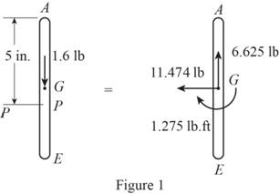
Two rotating rods in the vertical plane are connected by a slider block P of negligible mass. The rod attached at A has a weight of 1.6 lb and a length of 8 in. Rod BP weighs 2 lb and is 10 in. long and the friction between block P and AE is negligible. The motion of the system is controlled by a couple M applied to rod BP. Knowing that rod BP has a constant angular velocity of 20 rad/s clockwise, determine (a) the couple M, (b) the components of the force exerted on AE by block P.
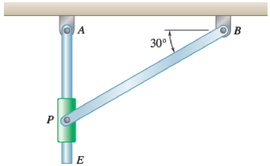
Fig. P16.141 and Fig. P16.142
(a)
Find the value of couple M.
Answer to Problem 16.141P
The value of couple M is
Explanation of Solution
Given information:
The weight of the rod AE is
The weight of the rod BP is
The length of the rod AE is
The length of the rod BP is
The angular velocity is
Calculation:
Consider the acceleration due to gravity as
Calculate the position vector
The position of P with respect to A.
The position of P with respect to B.
The position of P with respect to E.
The angular velocity of rod BP in vector form is
Calculate the velocity of rod BP
Substitute
Consider the relative angular velocity of rod AE as
Calculate the velocity of point P
Substitute
Resolving i and j components as shown below.
Calculate the acceleration of rod BP
Substitute 0 for
Calculate the acceleration of point P with respect to point E
Substitute
Calculate the acceleration of point P
Substitute
Resolving i and j components as shown below.
Calculate the mass of
For rod AE.
Substitute
For rod BP.
Substitute
Calculate the mass moment of inertia
For rod AE.
Substitute
For rod BP.
Substitute
Calculate the position vector
The position of mass center G with respect to the rod AE.
The position of mass center H with respect to the rod BP.
Calculate the acceleration of point G
Substitute
Calculate the acceleration of point H
Substitute 0 for
Calculate the inertial terms of the mass center
For rod AE.
For rod BP.
Calculate the effective couples at mass center
For rod AE.
For rod BP.
Sketch the Free Body Diagram of rod AE as shown in Figure 1.
Refer to Figure 1.
Apply the Equilibrium of moment about A as shown below.
Substitute
Sketch the Free Body Diagram of rod BP as shown in Figure 2.
Refer to Figure 2.
Apply the Equilibrium of moment about A as shown below.
Substitute
Hence, the couple M is
(b)
The components of the force exerted on AE by block.
Answer to Problem 16.141P
The components of the force exerted on AE by block is
Explanation of Solution
Given information:
The weight of the rod AE is
The weight of the rod BP is
The length of the rod AE is
The length of the rod BP is
The angular velocity is
Calculation:
Refer to part (a).
The components of the force exerted on AE by block
Therefore, the components of the force exerted on AE by block is
Want to see more full solutions like this?
Chapter 16 Solutions
VECTOR MECH...,STAT.+DYN.(LL)-W/ACCESS
Additional Engineering Textbook Solutions
Thermodynamics: An Engineering Approach
Manufacturing Engineering & Technology
Mechanics of Materials
Heat and Mass Transfer: Fundamentals and Applications
Foundations of Materials Science and Engineering
Vector Mechanics for Engineers: Statics


- The mechanism shown is one of two identical mechanisms attached to the two sides of a 200-lb uniform rectangular door. Edge ABC of the door is guided by wheels of negligible mass that roll in horizontal and vertical tracks. A spring with a constant k is attached to wheel B in such a way that its tension is zero when 0 = 30°, Knowing that the door is released from rest in the position 0 = 45° and reaches the vertical position with an angular velocity of 0.6 rad/s, determine the spring constant k.arrow_forwardThe 10-in.-radius brake drum is attached to a larger flywheel which is not shown. The total mass moment of inertia of the flywheel and drum is 22 lb ⋅ ft ⋅ s 2 and the coefficient of kinetic friction between the drum and the brake shoe is 0.41. Knowing that the initial angular velocity is 255 rpm clockwise, determine the force which must be exerted by the hydraulic cylinder at point B if the system is to stop in 85 revolutions.arrow_forwardThe 10-in.-radius brake drum is attached to a larger flywheel which is not shown. The total mass moment of inertia of the flywheel and drum is 22 lb ⋅ ft ⋅ s 2 and the coefficient of kinetic friction between the drum and the brake shoe is 0.41. Knowing that the initial angular velocity is 255 rpm clockwise, determine the force which must be exerted by the hydraulic cylinder at point B if the system is to stop in 85 revolutions. DO NOT ROUND OFF IN THE SOLUTION. ROUND OFF ONLY THE FINAL ANSWERarrow_forward
- A 255-lbf block is suspended from an inextensible cable which is wrapped around a drum of 1.75-ft radius rigidly attached to a flywheel. The drum and flywheel have a combined centroidal moment of inertia 12 lb . ft . s 2 . At the instant shown, the velocity of the block is unknown directed downward. Knowing that the bearing at A is poorly lubricated and that the bearing friction is equivalent to a couple M of magnitude 65 lb .ft, determine the velocity of the block before it has moved 3.5 ft downward if at S2 speed is 13.5ft/sarrow_forwardThe 10-in.-radius brake drum is attached to a larger flywheel which is not shown. The total mass moment of inertia of the flywheel and drum is 22 lb ⋅ ft ⋅ s 2 and the coefficient of kinetic friction between the drum and the brake shoe is 0.41. Knowing that the initial angular velocity is 255 rpm clockwise, determine the force which must be exerted by the hydraulic cylinder at point B if the system is to stop in 85 revolutions. determine the force which must be exerted by the hydraulic cylinder at point B if the system is to stop in 85 revolutions. DO NOT ROUND OFF IN THE SOLUTION. ROUND OFF ONLY IN 2 DECIMAL PLACE IN THE FINAL ANSWER.arrow_forwardA 48-kg advertising panel of length 2a = 2.4 m and width 2b = 1.6 m is kept rotating at a constant rate w1 about its horizontal axis by a small electric motor attached at A to frame ACB. This frame itself is kept rotating at a constant rate w2 about a vertical axis by a second motor attached at C to the column CD. Knowing that the panel and the frame complete a full revolution in 6 s and 12 s, respectively, express, as a function of the angle 0, the dynamic reaction exerted on column CD by its support at D.arrow_forward
- A 1200-kg satellite designed to study the sun has an angular velocity of w0 = (0.050 rad/s)i + (0.075 rad/s)k when two small jets are activated at A and B in a direction parallel to the y axis. Knowing that the coordinate axes are principal centroidal axes, that the radii of gyration of the satellite are and that each jet produces a 50-N thrust, determine (a ) the required operating time of each jet if the angular velocity of the satellite is to be reduced to zero, (b ) the resulting change in the velocity of the mass center G.arrow_forwardDisk A, of weight 5 lb and radius r = 3 in., is at rest when it is placed in contact with a belt that moves at a constant speed v = 50 ft/s. Knowing that μk = 0.20 between the disk and the belt, determine the time required for the disk to reach a constant angular velocity.arrow_forwardTwo identical 4-lb slender rods AB and BC are connected by a pin at B and by the cord AC. The assembly rotates in a vertical plane under the combined effect of gravity and a 6-lb·ft couple M applied to rod AB. Knowing that in the position shown the angular velocity of the assembly is zero, determine (a) the angular acceleration of the assembly, (b) the tension in cord AC.arrow_forward
- The double pulley shown has a mass of 15 kg and a centroidal radius of gyration of 160 mm. Cylinder A and block B are attached to cords that are wrapped on the pulleys as shown. The coefficient of kinetic friction between block and the surface is 0.2. Knowing that the system is at rest in the position shown when a constant force P = 200 N is applied to cylinder A , determine (a ) the velocity of cylinder A as it strikes the ground, (b ) the total distance that block B moves before coming to rest.arrow_forwardA bar of mass m = 5 kg is held as shown between four disks each of mass m’ = 2 kg and radius r = 75 mm. Knowing that the forces exerted on the disks are sufficient to prevent slipping and that the bar is released from rest, for each of the cases shown, determine the velocity of the bar after it has moved through the distance h.arrow_forward
 Elements Of ElectromagneticsMechanical EngineeringISBN:9780190698614Author:Sadiku, Matthew N. O.Publisher:Oxford University Press
 Mechanics of Materials (10th Edition)Mechanical EngineeringISBN:9780134319650Author:Russell C. HibbelerPublisher:PEARSON
 Thermodynamics: An Engineering ApproachMechanical EngineeringISBN:9781259822674Author:Yunus A. Cengel Dr., Michael A. BolesPublisher:McGraw-Hill Education
 Control Systems EngineeringMechanical EngineeringISBN:9781118170519Author:Norman S. NisePublisher:WILEY
 Mechanics of Materials (MindTap Course List)Mechanical EngineeringISBN:9781337093347Author:Barry J. Goodno, James M. GerePublisher:Cengage Learning
 Engineering Mechanics: StaticsMechanical EngineeringISBN:9781118807330Author:James L. Meriam, L. G. Kraige, J. N. BoltonPublisher:WILEY