
Introductory Circuit Analysis; Laboratory Manual For Introductory Circuit Analysis Format: Kit/package/shrinkwrap
13th Edition
ISBN: 9780134297446
Author: Boylestad, Robert L.
Publisher: Prentice Hall
expand_more
expand_more
format_list_bulleted
Concept explainers
Videos
Textbook Question
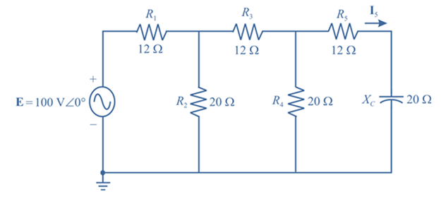
Chapter 17, Problem 14P
Find the current I5 for the network in Fig. 17.51. Note the effect of one reactive element on the resulting calculations.
Expert Solution & Answer
Want to see the full answer?
Check out a sample textbook solution
Students have asked these similar questions
A transmission line has a characteristic impedance of ? = 21.05∠60.4 with propagation constant of 7.561 ? 10-3+ ? 0.002863 . Calculate the primary constants at an angular frequency of 5000 rad/sec.
A 144.0cm parabolic reflector antenna has a 6m effective aperture. Show the gain in dB for a 10 GHz anticipated frequency.
A telephone line having a bandwidth of 3 kHz is assigned for data communication. The SNR is 3050. What will be the capacity for the channel?
Chapter 17 Solutions
Introductory Circuit Analysis; Laboratory Manual For Introductory Circuit Analysis Format: Kit/package/shrinkwrap
Ch. 17 - For theseries-parallel network in Fig.17.38. a....Ch. 17 - For the network in Fig. 17.39: a. Find the total...Ch. 17 - For the network in FIg. 17.40: a. Find the total...Ch. 17 - For the network in Fig. 17.41: a. Find the total...Ch. 17 - For the network in Fig. 17.42: a. Find the current...Ch. 17 - For the network in Fig. 17.43: a. Find the current...Ch. 17 - For the network in Fig. 17.44: a. Find the current...Ch. 17 - For the network in Fig. 17.45: a. Find the source...Ch. 17 - For the network of Fig. 17.46: a. Find the voltage...Ch. 17 - For the network in Fig. 17.47: a. Find the total...
Ch. 17 - For the network in Fig. 17.48: a. Find the total...Ch. 17 - For the network of Fig. 17.49: a. Find the total...Ch. 17 - For the network of Fig. 17.50: a. Find the total...Ch. 17 - Find the current I5 for the network in Fig. 17.51....Ch. 17 - Find the average power delivered to R5 in Fig....Ch. 17 - For the ladder network of Fig. 17.53: a. Find the...Ch. 17 - Prob. 17PCh. 17 - PSpice or Multisim For Problems 15 through 18, use...Ch. 17 - PSpice or Multisim For Problems 15 through 18, use...Ch. 17 - PSpice or Multisim For Problems 15 through 18, use...Ch. 17 - PSpice or Multisim For Problems 15 through 18, use...
Knowledge Booster


Learn more about
Need a deep-dive on the concept behind this application? Look no further. Learn more about this topic, electrical-engineering and related others by exploring similar questions and additional content below.Similar questions
- The ERP of a transmitting station is specified as 17W in a given direction. Express this as an EIRP in dBm.arrow_forwardAn FM signal , 2000 sin(2π x 108t + 2sin πx 104t), is applied to a 50 ohms antenna. Determine: (a) The intelligence signal frequency. (b) The bandwidth (using the two methods) (c) The power in the largest and smallest side bands.arrow_forward1. An AM standard broadcast station has a Lower sideband and an upper side band frequency of 770KHz and 780KHz, respectively. If the AM station is transmitting a frequency of 775KHz, calculate the: a. Total bandwidth occupied by the AM station.arrow_forward
- 1 (AM) An AM transmitter has a 1KW carrier power and is modulated by a sinusoidal tone. If you have 0.7 modulation index, what is the total power necessary for transmission?arrow_forwardA planar LED is fabricated from gallium arsenide which has a refractive indexof 3.6. Calculate the optical power emitted into air as a percentage of theinternal optical power for the device when the transmission factor at thecrystal–air interface is 0.68. When the optical power generated internally is 50% of the electric powersupplied, determine the external power efficiency.arrow_forwardAn RC phase-shift oscillator, using an FET, uses three identical phase-shifting networks in which R = 100 kΩ and C = 64.79 pF. Calculate the frequency of the oscillations and the value of RD. The FET has gm = 5 mmhos and rd = 50 kΩ.arrow_forward
- Answer the following on a clean sheet of paper. Take a photo of your answer sheet then upload here. Assuming that an oscilloscope displays a Vmax of 5.22V and Vmin of 1.33V. Calculate the percentage of modulation. (5 points) Three (3) AM broadcast stations are spaced at 18 kHz, beginning at 73 kHz. Each station is allowed to transmit modulating up to 6 kHz. Compute for the upper and lower sidebands of each station and plot it in the frequency domain. (15 points) Given a Vmax of 7.45V and a modulation index of 0.691, calculate for Vmin. (5 points) A station is given a carrier frequency of 88 kHz. Having a modulating frequency of 12 kHz, compute for the upper and lower sidebands of the station. (5 points)arrow_forwardYou have a broadcasting station on the frequency of 107.3 MHz and radiate with a power of 230 KWatt with a 3 dBi antenna, if we have a receiver 50 km away with a receiving power of -112.28 dBm. What will be the power gain expressed in decibels of the receiving antenna.arrow_forwardIn an AM transmission system the transmitter current was found to be 9.A. If the carrier signal is the only one to be sent and later increases to 10.72 A. Also if the carrier is modulated by a single sinusoidal wave, compute the percentage modulation. Again find the current of the antenna if the percentage of modulation changes 85%.arrow_forward
- Q5- If an AM signal is represented by, V = (10 + 2 Sin ( 2π × 5 × 103 t) ) Sin ( 2π × 0.5 × 106 t) 1- Calculate the values of the frequencies of carrier and modulating signals. 2- Calculate the value of modulation index. 3- Calculate the value of bandwidth of this signal. 4- Calculate the power in the carrier and the sidebands, if an AM signal has a total power of 48 Watts with 45% modulation.arrow_forwardCalculate the Fourier sequence coefficients of the signals given in the attached file.arrow_forwardAn RF link, which includes transmitting and receiving antennas, operates at 10 GHz. The transmitting and receiving antennas are separated by a distance of 1 m. The transmitting and receiving antenna both have a gain of 10 dBi. If 20 dBm is fed to the transmitting antenna, determines the received power in dBm.arrow_forward
arrow_back_ios
SEE MORE QUESTIONS
arrow_forward_ios
Recommended textbooks for you
 Introductory Circuit Analysis (13th Edition)Electrical EngineeringISBN:9780133923605Author:Robert L. BoylestadPublisher:PEARSON
 Delmar's Standard Textbook Of ElectricityElectrical EngineeringISBN:9781337900348Author:Stephen L. HermanPublisher:Cengage Learning
 Programmable Logic ControllersElectrical EngineeringISBN:9780073373843Author:Frank D. PetruzellaPublisher:McGraw-Hill Education
 Fundamentals of Electric CircuitsElectrical EngineeringISBN:9780078028229Author:Charles K Alexander, Matthew SadikuPublisher:McGraw-Hill Education
 Electric Circuits. (11th Edition)Electrical EngineeringISBN:9780134746968Author:James W. Nilsson, Susan RiedelPublisher:PEARSON
 Engineering ElectromagneticsElectrical EngineeringISBN:9780078028151Author:Hayt, William H. (william Hart), Jr, BUCK, John A.Publisher:Mcgraw-hill Education,
Introductory Circuit Analysis (13th Edition)
Electrical Engineering
ISBN:9780133923605
Author:Robert L. Boylestad
Publisher:PEARSON
Delmar's Standard Textbook Of Electricity
Electrical Engineering
ISBN:9781337900348
Author:Stephen L. Herman
Publisher:Cengage Learning
Programmable Logic Controllers
Electrical Engineering
ISBN:9780073373843
Author:Frank D. Petruzella
Publisher:McGraw-Hill Education
Fundamentals of Electric Circuits
Electrical Engineering
ISBN:9780078028229
Author:Charles K Alexander, Matthew Sadiku
Publisher:McGraw-Hill Education
Electric Circuits. (11th Edition)
Electrical Engineering
ISBN:9780134746968
Author:James W. Nilsson, Susan Riedel
Publisher:PEARSON
Engineering Electromagnetics
Electrical Engineering
ISBN:9780078028151
Author:Hayt, William H. (william Hart), Jr, BUCK, John A.
Publisher:Mcgraw-hill Education,
Understanding Amplitude Modulation; Author: Rohde Schwarz;https://www.youtube.com/watch?v=I46eP8uZh_Y;License: Standard Youtube License