
Introductory Circuit Analysis; Laboratory Manual For Introductory Circuit Analysis Format: Kit/package/shrinkwrap
13th Edition
ISBN: 9780134297446
Author: Boylestad, Robert L.
Publisher: Prentice Hall
expand_more
expand_more
format_list_bulleted
Concept explainers
Videos
Textbook Question
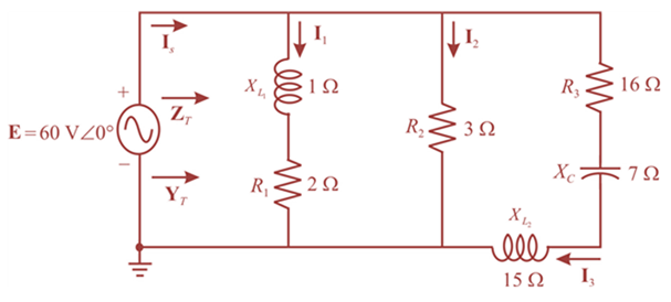
Chapter 17, Problem 10P
For the network in Fig. 17.47:
a. Find the total impedance ZT and the admittance YT.
b. Find the current I1, I2, an I3.
c. Verify Kirchhoff’s current law by showing that
d. Find the power factor of the network, and indicate whether it is leading or lagging.
Expert Solution & Answer
Want to see the full answer?
Check out a sample textbook solution
Students have asked these similar questions
A transmission line has a characteristic impedance of ? = 21.05∠60.4 with propagation constant of 7.561 ? 10-3+ ? 0.002863 . Calculate the primary constants at an angular frequency of 5000 rad/sec.
The primary constants of a uniform line 67.19 meters long, have the following values at 171.31 MHz: R = 5215.2491 mΩ / m, L = 1017.7428 nH / m, C = 69.8857 pF / m and G = 43.2532 µS / m. Decide:
a) How much the characteristic impedance and the attenuation coefficient are worth per unit length (in mdB / m) of the same, at said frequency.
A transmission line has the following primary constants: resistance R = 15 /loop km, inductance L = 3.4 mH/loop km, conductance G = 3µS/km and capacitance C = 10 nF/km. Determine the characteristic impedance of the line when the frequency is 2 kHz
Chapter 17 Solutions
Introductory Circuit Analysis; Laboratory Manual For Introductory Circuit Analysis Format: Kit/package/shrinkwrap
Ch. 17 - For theseries-parallel network in Fig.17.38. a....Ch. 17 - For the network in Fig. 17.39: a. Find the total...Ch. 17 - For the network in FIg. 17.40: a. Find the total...Ch. 17 - For the network in Fig. 17.41: a. Find the total...Ch. 17 - For the network in Fig. 17.42: a. Find the current...Ch. 17 - For the network in Fig. 17.43: a. Find the current...Ch. 17 - For the network in Fig. 17.44: a. Find the current...Ch. 17 - For the network in Fig. 17.45: a. Find the source...Ch. 17 - For the network of Fig. 17.46: a. Find the voltage...Ch. 17 - For the network in Fig. 17.47: a. Find the total...
Ch. 17 - For the network in Fig. 17.48: a. Find the total...Ch. 17 - For the network of Fig. 17.49: a. Find the total...Ch. 17 - For the network of Fig. 17.50: a. Find the total...Ch. 17 - Find the current I5 for the network in Fig. 17.51....Ch. 17 - Find the average power delivered to R5 in Fig....Ch. 17 - For the ladder network of Fig. 17.53: a. Find the...Ch. 17 - Prob. 17PCh. 17 - PSpice or Multisim For Problems 15 through 18, use...Ch. 17 - PSpice or Multisim For Problems 15 through 18, use...Ch. 17 - PSpice or Multisim For Problems 15 through 18, use...Ch. 17 - PSpice or Multisim For Problems 15 through 18, use...
Knowledge Booster


Learn more about
Need a deep-dive on the concept behind this application? Look no further. Learn more about this topic, electrical-engineering and related others by exploring similar questions and additional content below.Similar questions
- DISCRETE TIME GIVEN SYSTEM.Determine the poles and zeros of this system, and show how they relate to each other.The system is only marginally stable True False Find the frequency response of this system. ( NEED NEAT HANDWRITTEN SOLUTION ONLY OTHERWISE DOWNVOTE).arrow_forwardA medium transmission line has a total series impedance of Z = (4 + j12) Ω and a shunt admittance of Y = j0.0075 S. Determine the following transmission line constants for a T network: a) A b) B c) C d) Darrow_forwarda) A short transmission line has a sending end voltage of VS and a receiving end voltage of VR. If the receiving end current is IR and the reactance of the line is X, derive an equation for the sending end apparent power. b) based on your answer to a) deduce equations for the active power and reactive powerarrow_forward
- A HV transmission line having receiving end load is 300MVA, 50 Hz line from poin A to point B. Resistance 0.13 ohm/KM , for 160 KM Inductance XL= 0.4 ohm per kilometer Parallel admittance j318 × 10-6 Power Factor 0.8770, 0.8477 lagging, unity and 0.8770, 0.8477 leading Assume desired voltage at the receiving end of the transmission line is not less than 380kV., if the line is supplying rated voltage and apparent power at various power factors given Estimate : a. Sending end voltages b. Voltage regulation c. Efficiency of the transmission line d. Give a technical explanations on the results obtainedarrow_forwardcharacteristic impedance z0 = 50 ohms is a short-circuited coaxial (coaxial) cable with a length d = 0.3λ component is wanted to be made. Use Its frequency is f = 8 GHz. (a) Identify the component. (b) Find the impedance value of the component. (c) Find the parameter value of the component. lesson:electrical and electronical engineeringarrow_forwardThe parameters of a certain transmission line operating at ω = 6×10⁸ rad/s are L = 0.35μH/m, C = 40 pF/m, G = 75 μS/m, and R = 17 Ω/m. Find α, β, λ, and Z0.arrow_forward
- PRACTICE 10.11 Determine the admittance (in rectangular form) of (a) an impedance Z 1000+ j400 2: (b) a network consisting of the parallel combination of an 800 52 resistor, a 1 mH inductor, and a 2 nF capacitor, if = 1 Mrad/s; (c) a network consisting of the series com- bination of an 800 2 resistor, a 1 mH inductor, and a 2 nF capacitor, if ∞ = 1 Mrad/s. Ans: 0.862-j0.345 mS: 1.25 + j1 mS: 0.899- j0.562 ms.arrow_forwardTransmission line with a load Zl = 100 + i80 ohm with characteristic impedance of Z0 = 5 ohm is designed. The transmission line operates at 100 MHz, where is matched with a shunt single- stub tuner. a)Calculate the stub positions. b)Calculate the stub length where open circuit stub is used. c) Calculate the stub length where short circuit stub is used.arrow_forward. In Japan, a simple series RC circuit is connected to a socket with v(t) = 339cos(100piT) V. If R = 2 k2 and C = 100 microF, (a) gives the complex frequency of the corresponding voltage V(s) in the frequency domain. (tí) Work in the frequency domain to express the current I(s) flowing through the circuit, (c) Determine i (t)..arrow_forward
- The load impedance ZL, which is adjusted to transfer the maximum power in the circuit below,Calculate the value and the maximum transmitted power.arrow_forwardConsider an LTI system with frequency response H(ejw) as given below H(ejw) = (1-e –j2w)/(1+1/2e –j4w) Find y[n] for x[n]= sin(πn/2+π/4).arrow_forwardA transmission line has generalized circuit constants are A=0.93+j0.016,B=20+j140.The load at the receiving end is 60MVA, 50HZ, 0.8 power factor lagging. The voltage at the supply end is 132KV. Caluclate the load voltage and voltage regulation,Use nominal-π approximation.arrow_forward
arrow_back_ios
SEE MORE QUESTIONS
arrow_forward_ios
Recommended textbooks for you
 Introductory Circuit Analysis (13th Edition)Electrical EngineeringISBN:9780133923605Author:Robert L. BoylestadPublisher:PEARSON
 Delmar's Standard Textbook Of ElectricityElectrical EngineeringISBN:9781337900348Author:Stephen L. HermanPublisher:Cengage Learning
 Programmable Logic ControllersElectrical EngineeringISBN:9780073373843Author:Frank D. PetruzellaPublisher:McGraw-Hill Education
 Fundamentals of Electric CircuitsElectrical EngineeringISBN:9780078028229Author:Charles K Alexander, Matthew SadikuPublisher:McGraw-Hill Education
 Electric Circuits. (11th Edition)Electrical EngineeringISBN:9780134746968Author:James W. Nilsson, Susan RiedelPublisher:PEARSON
 Engineering ElectromagneticsElectrical EngineeringISBN:9780078028151Author:Hayt, William H. (william Hart), Jr, BUCK, John A.Publisher:Mcgraw-hill Education,
Introductory Circuit Analysis (13th Edition)
Electrical Engineering
ISBN:9780133923605
Author:Robert L. Boylestad
Publisher:PEARSON
Delmar's Standard Textbook Of Electricity
Electrical Engineering
ISBN:9781337900348
Author:Stephen L. Herman
Publisher:Cengage Learning
Programmable Logic Controllers
Electrical Engineering
ISBN:9780073373843
Author:Frank D. Petruzella
Publisher:McGraw-Hill Education
Fundamentals of Electric Circuits
Electrical Engineering
ISBN:9780078028229
Author:Charles K Alexander, Matthew Sadiku
Publisher:McGraw-Hill Education
Electric Circuits. (11th Edition)
Electrical Engineering
ISBN:9780134746968
Author:James W. Nilsson, Susan Riedel
Publisher:PEARSON
Engineering Electromagnetics
Electrical Engineering
ISBN:9780078028151
Author:Hayt, William H. (william Hart), Jr, BUCK, John A.
Publisher:Mcgraw-hill Education,
How do Electric Transmission Lines Work?; Author: Practical Engineering;https://www.youtube.com/watch?v=qjY31x0m3d8;License: Standard Youtube License