
Applied Statics and Strength of Materials (6th Edition)
6th Edition
ISBN: 9780133840728
Author: Limbrunner
Publisher: PEARSON
expand_more
expand_more
format_list_bulleted
Concept explainers
Videos
Textbook Question
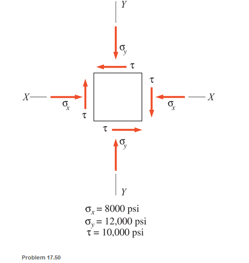
Chapter 17, Problem 17.50SP
An element of a machine member is subjected to the stresses shown. Calculate the magnitude and direction of the principal stresses and the maximum shear stress. Use the analytical approach.
Expert Solution & Answer
Want to see the full answer?
Check out a sample textbook solution
Students have asked these similar questions
Please correct solution
A differential stress element has the following stress components:
Ox = 20 ksi, y = -10 ksi, Txy = -5 ksi.
Consider a point in a structural member that is subjected to plane stress. Normal and shear stresses acting on horizontal and vertical planes at the are shown. Calculate
a. The magnitude and nature of the principal stresses
b. The magnitude of the maximum shear stresses in the plane of the given system
c. The direction of the plane on which these stresses act. Confirm your answer by means of a mohr's stress circle diagram and from the diagram determine the magnitude of the normal stress on a plane inclined at 30 degrees counterclockwise the plane on the X axis stress
Chapter 17 Solutions
Applied Statics and Strength of Materials (6th Edition)
Ch. 17 - Prob. 17.1PCh. 17 - A horizontal 30-ft simple span beam is supported...Ch. 17 - A 1-in.-by-4-in, steel bar is subjected to the...Ch. 17 - A W410100 structural steel wide-flange section is...Ch. 17 - A W1272 structural steel wide-flange section is...Ch. 17 - A solid steel shaft 3 in. in diameter and 4 ft...Ch. 17 - A short compression member is subjected to a...Ch. 17 - With reference to Problem 17.7, calculate the...Ch. 17 - A section of a 51-mm-diameter standard-weight...Ch. 17 - For the pipe of Problem 17.9, compute the maximum...
Ch. 17 - A concrete pedestal is in the shape of a cube and...Ch. 17 - 17.12 For the pedestal of Problem 17.11, assume...Ch. 17 - 17.13 Rework Problem 17.11, but assume that the...Ch. 17 - A 12-in-square concrete pedestal is subjected to a...Ch. 17 - 17.15 A short compression member is subjected to a...Ch. 17 - A rectangular concrete footing, 4 ft by 8 ft in...Ch. 17 - The bending and shear stresses developed at a...Ch. 17 - Stresses developed at a point in a machine part...Ch. 17 - Calculate the principal stresses at points A and B...Ch. 17 - 17.20 Rework Problem 17.19 using P = 8000 lb and...Ch. 17 - 17.21 A 1-in.-square steel bar is subjected to an...Ch. 17 - 17.22 A bar having a cross-sectional area of 6...Ch. 17 - Rework Problem 17.22, changing the load to a...Ch. 17 - Solve Problem l7.17 using Mohr’s circle.Ch. 17 - For the elements shown in Problem 17.18, use...Ch. 17 - Solve Problem 17.19 using Mohr’s circle.Ch. 17 - In Problem 17.19, change the load to 8000 lb and...Ch. 17 - For the following computer problems, any...Ch. 17 - For the following computer problems, any...Ch. 17 - For the following computer problems, any...Ch. 17 - For the following computer problems, any...Ch. 17 - A 4-in.-by-8-in. (S4S) Douglas fir timber beam is...Ch. 17 - A horizontal flexural member (a girt) in the wall...Ch. 17 - A simply supported W1850 structural steel...Ch. 17 - A steel link in a machine is designed to avoid...Ch. 17 - 17.36 An 8-in-square (S4S) vertical timber post is...Ch. 17 - A short 3-in.-square steel bar with a...Ch. 17 - A timber member 150 mm by 250 mm (S4S) is loaded...Ch. 17 - A concrete wall 8 ft high and 3 ft thick is...Ch. 17 - 17.40 A short compression member is subjected to a...Ch. 17 - 17.41 Calculate the maximum eccentric load that...Ch. 17 - A short compression member is subjected to two...Ch. 17 - 17.43 Calculate the force P that may be applied to...Ch. 17 - 17.44 A load of 1000 lb is supported on a...Ch. 17 - 17.45 A short compression member is subjected to...Ch. 17 - 17.46 A structural steel wide-flange section is...Ch. 17 - 17.47 A cast-iron frame for a piece of industrial...Ch. 17 - 17.48 The assembly shown is used in a machine. It...Ch. 17 - 17.49 A 50-mm-diameter solid steel shaft is...Ch. 17 - An element of a machine member is subjected to the...Ch. 17 - 17.51 A short-span cantilever built-up beam has...Ch. 17 - Solve Problem 17.50 using Mohr’s circle.Ch. 17 - 17.53 A cantilever beam is subjected to an...Ch. 17 - A 6-in.-diameter solid shaft is subjected to a...Ch. 17 - Rework parts (b) and (c) of Example 17.7 using...
Knowledge Booster


Learn more about
Need a deep-dive on the concept behind this application? Look no further. Learn more about this topic, mechanical-engineering and related others by exploring similar questions and additional content below.Similar questions
- -4. - An element in plane stress is subjected to stresses ??x= 105 MPa, ??y= 75 MPa, and sxy= 25 MPa (see the figure for Problem 7.3-1). Determine the principal stresses and show them on a sketch of a properly oriented element.arrow_forwardAn element on the top surface of the fuel tanker in Problem 7.2-1 is in biaxial stress and is subjected to stresses a = -48 MPa and ay = 19 MPa, as shown in the figure. Using Mohr’s circle, determine the following. (a) The stresses acting on an clement oriented at a counterclockwise angle ?? = 25° from the x axis. (b) The maximum shear stresses and associated normal stresses. Show all results on sketches of properly oriented elements.arrow_forwardAn element on the top surface of the fuel tanker in Problem 7.2-1 is in biaxial .is in the and is subjected to stresses a, = 6250 psi and a. = -1750 psi, as shown in the figure. Using Mohr s circle, determine the following: (a) The stresses acting on an element oriented at a counterclockwise angle ? = 550 from the x axis. (b) The maximum shear stresses and associated norm al stresses. Show all results on sketches of properly oriented elements.arrow_forward
- -9The stresses acting on element B in the web of a wide-flange beam are found to be 14,000 psi compression in the horizontal direction and 2600 psi compression in the vertical direction. Also, shear stresses of magnitude 3800 psi act in the direct ions shown (see the figure for Problem 7.2-9). Determine the maximum shear stresses and associated normal stresses and show them on a sketch of a properly oriented element.arrow_forwardSolve the preceding problem for an element in plane stress on the bottom surface of a fuel tanker (figure part a); stresses are sx= 105 MPa, sy. = 75 MPa, and ??xy= 25 MPa. Determine the stresses acting on an element oriented at an angle ?? = 40° from the x axis, where the angle is positive when counterclockwise. Show these stresses on a sketch of an element oriented at the angle ??.arrow_forward‘7.3-11 The stresses on an element are sx= -300 psi and sy= 600 psi. Find the maximum shear stresses on the element and show them on a sketch of a properly oriented clement.arrow_forward
- The stresses acting on element A in the web of a train rail are found to be 40 M Pa tension in the horizontal direction and 160 MPa, compression in the vertical direct ion. Also, shear stresses of magnitude 54 MPa act in the directions shown (see the figure b for Problem 7.2-5). Determine the principal stresses and show them on a sketch of a properly oriented element.arrow_forwardAn element in plane stress from the fuselage of an airplane is subjected to compressive stresses of magnitude 35 MPa in the horizontal direction and tensile stresses of magnitude 6.5 MPa in the vertical direct ion. Also, shear stresses of magnitude 12.5 MPa act in the directions shown (see the figure for Problem 7.2-8). Determine the maximum shear stresses and associated normal stresses and show them on a sketch of a properly oriented element.arrow_forwardA simply supported wood beam is subjected to point load P at mid-span. The stresses on element C are known to be ??x=-92 psi and txy= -7 psi. Find the principal stresses on the element and show them on a sketch of a properly oriented clement.arrow_forward
- A simply supported beam is subjected to point load P at mid-span. The normal stress on an element at mid-span is known to be ??x= 1.5 ksi. Determine the element stresses lilt is rotated through angle ? = 450• Show these stresses on a sketch of an element oriented at that angle.arrow_forwardAn element in plane stress on the fuselage of an airplane (figure part a) is subjected to compressive stresses with a magnitude of 42 MPa in the horizontal direction and tensile stresses with a magnitude of 9.5 MPa in the vertical direction (sec figure part b). Also, shear stresses with a magnitude of 15.5 MPa act in the directions shown. Determine the stresses acting on an element oriented at a clockwise angle of 40g from the horizontal. Show these stresses on a sketch of an element oriented at this angle.arrow_forwardThe normal and shear stresses acting on element A are 6500 psi, 17,300 psi, and 2900 psi (see the figure b for Problem 7.2-5). Determine the maximum shear stresses and associated normal stresses and show them on a sketch of a properly oriented element.arrow_forward
arrow_back_ios
SEE MORE QUESTIONS
arrow_forward_ios
Recommended textbooks for you
 Mechanics of Materials (MindTap Course List)Mechanical EngineeringISBN:9781337093347Author:Barry J. Goodno, James M. GerePublisher:Cengage Learning
Mechanics of Materials (MindTap Course List)
Mechanical Engineering
ISBN:9781337093347
Author:Barry J. Goodno, James M. Gere
Publisher:Cengage Learning
Understanding Stress Transformation and Mohr's Circle; Author: The Efficient Engineer;https://www.youtube.com/watch?v=_DH3546mSCM;License: Standard youtube license