
Concept explainers
Videos
Find the current through the inductor
Answer to Problem 39P
The current through the inductor
Explanation of Solution
Given data:
Refer to Figure 17.75(a) and 17.75(b) in the textbook.
The inductor L is
The capacitor
Formula used:
Write the general expression for Fourier series expansion.
Write the expression to calculate the fundamental angular frequency.
Here,
Calculation:
Refer to Figure 17.73(a) in the textbook.
The source voltage
The time period of Figure 17.75(a) is,
Substitute 2 for T in equation (2) to find the angular frequency
Finding the Fourier coefficient
Applying equation (3) in equation (4) as follows,
The above equation becomes,
Finding the Fourier coefficient
Applying equation (3) in equation (5) as follows,
Finding the Fourier coefficient
Applying equation (3) in equation (6) as follows,
Simplify the equation as follows,
The above equation becomes,
Substituting the Fourier coefficients in equation (1) as follows,
Refer to Figure 17.75(b) in the textbook.
For the DC component, the current
The inductor acts as a short circuit for DC.
For the kth harmonic,
Consider Figure 17.75(b) for AC analysis.
The impedance of the inductor is calculated as follows,
Substitute
The impedance of the capacitor is calculated as follows,
Substitute
The modified circuit is shown in Figure 1.
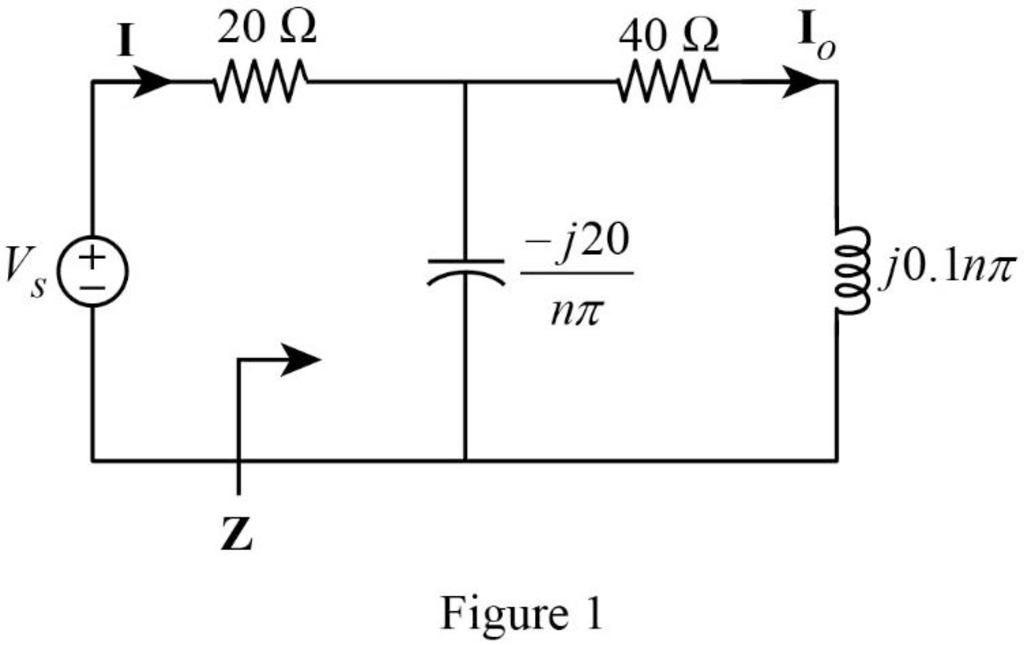
In Figure 1, the impedance is,
Simplify the above equation as follows,
The impedance
Substitute
The current
Substitute
The current
Substitute
Simplify the equation as follows,
The magnitude and phase angle of the current
In the time domain,
Where,
The phase angle
And,
The current
Conclusion:
Thus, the current through the inductor
Want to see more full solutions like this?
Chapter 17 Solutions
FUND.OF ELECTRIC CIRCUITS(LL)-W/CONNECT


- 1. Derive the Fourier series for the periodic current shown .2. Repeat (a) if the vertical reference axis is shifted T/2 units to theleft.arrow_forwardQ3 Assume that a periodic signal has a fundamental angular frequency of ω0. Which Fourier Series component of the signal has angular frequency of 5ω0.arrow_forwardFind the signal x[n] with period 8 whose Fourier series coefficients are given below.arrow_forward
- An alternating voltage is given by v=100 sin(50πt −0.30)V. Which of the following statements is true? a. The r.m.s. voltage is 100V b. The periodic time is 20 ms c. The frequency is 25 Hz d. The voltage is leading v=100 sin 50πt by 0.30 radians Which one is mainly used for a periodic signals? a. None of the above b. Both c and d c. Fourier series d. Fourier transformarrow_forwardSignals And Systems Calculate the fourier series coefficients of given signalarrow_forward1) Write down the fourier transform of some standard signals : A) Unit step function. B) Triangular pulse.arrow_forward
- Determine if periodic or non periodic then solve the fourier seriesarrow_forwardg(x) equals {0, -5≤x<0} {3, 0<x<5} Find the expansion of the function above in a fourier series considering the period is ten.arrow_forwardFind the fourier coefficients Ck of the periodic sequence below: ASAParrow_forward
- Find trigonometric Fourier series expansion of the following plotted signals.arrow_forwardDetermine the given signal if it is Periodic or Non-periodic. When it is Periodic, calculate the Fundamental time period and Fundamental Frequency.arrow_forwardConsider the Fourier series for the periodic function: a(t) = 4(cost)(sin4t) The Fourier coefficient C1 of the exponential series is: Select one: 1 ejT/2 e-jn/2arrow_forward
 Introductory Circuit Analysis (13th Edition)Electrical EngineeringISBN:9780133923605Author:Robert L. BoylestadPublisher:PEARSON
 Delmar's Standard Textbook Of ElectricityElectrical EngineeringISBN:9781337900348Author:Stephen L. HermanPublisher:Cengage Learning
 Programmable Logic ControllersElectrical EngineeringISBN:9780073373843Author:Frank D. PetruzellaPublisher:McGraw-Hill Education
 Fundamentals of Electric CircuitsElectrical EngineeringISBN:9780078028229Author:Charles K Alexander, Matthew SadikuPublisher:McGraw-Hill Education
 Electric Circuits. (11th Edition)Electrical EngineeringISBN:9780134746968Author:James W. Nilsson, Susan RiedelPublisher:PEARSON
 Engineering ElectromagneticsElectrical EngineeringISBN:9780078028151Author:Hayt, William H. (william Hart), Jr, BUCK, John A.Publisher:Mcgraw-hill Education,