
Introductory Circuit Analysis (13th Edition)
13th Edition
ISBN: 9780133923605
Author: Robert L. Boylestad
Publisher: PEARSON
expand_more
expand_more
format_list_bulleted
Concept explainers
Videos
Textbook Question
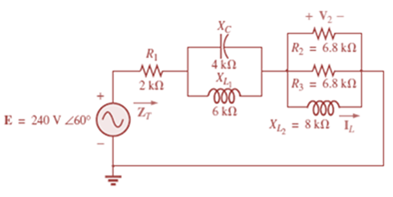
Chapter 17, Problem 4P
For the network in Fig. 17.41:
a. Find the total impedance ZT.
b. Calculate the voltage V2 and the current IL.
c. Find the power factor of the network.
Expert Solution & Answer
Want to see the full answer?
Check out a sample textbook solution
Students have asked these similar questions
A transmission line has a characteristic impedance of ? = 21.05∠60.4 with propagation constant of 7.561 ? 10-3+ ? 0.002863 . Calculate the primary constants at an angular frequency of 5000 rad/sec.
If the transmitter has a power of 8W (ignoring feedline losses and mismatch), find:
the power delivered to the receiver (in dBm). Round off your answers into two decimal places.
A 40ft transmission line has a phase shift coefficient of 40radians/meter, find its wavelength.
Chapter 17 Solutions
Introductory Circuit Analysis (13th Edition)
Ch. 17 - For theseries-parallel network in Fig.17.38. a....Ch. 17 - For the network in Fig. 17.39: a. Find the total...Ch. 17 - For the network in FIg. 17.40: a. Find the total...Ch. 17 - For the network in Fig. 17.41: a. Find the total...Ch. 17 - For the network in Fig. 17.42: a. Find the current...Ch. 17 - For the network in Fig. 17.43: a. Find the current...Ch. 17 - For the network in Fig. 17.44: a. Find the current...Ch. 17 - For the network in Fig. 17.45: a. Find the source...Ch. 17 - For the network of Fig. 17.46: a. Find the voltage...Ch. 17 - For the network in Fig. 17.47: a. Find the total...
Ch. 17 - For the network in Fig. 17.48: a. Find the total...Ch. 17 - For the network of Fig. 17.49: a. Find the total...Ch. 17 - For the network of Fig. 17.50: a. Find the total...Ch. 17 - Find the current I5 for the network in Fig. 17.51....Ch. 17 - Find the average power delivered to R5 in Fig....Ch. 17 - For the ladder network of Fig. 17.53: a. Find the...Ch. 17 - Prob. 17PCh. 17 - PSpice or Multisim For Problems 15 through 18, use...Ch. 17 - PSpice or Multisim For Problems 15 through 18, use...Ch. 17 - PSpice or Multisim For Problems 15 through 18, use...Ch. 17 - PSpice or Multisim For Problems 15 through 18, use...
Additional Engineering Textbook Solutions
Find more solutions based on key concepts
Assume a telephone signal travels through a cable at two-thirds the speed of light. How long does it take the s...
Electric Circuits (10th Edition)
Analog Voltmeter Design Figure P2-98(a) shows a voltmeter circuit consisting of a D'Arsonval meter, two series ...
ANALYSIS+DESIGN OF LINEAR CIRCUITS(LL)
The voltage source of the circuit shown in Fig. P1.29 is given by s(t)=25cos(4104t45)(V). Obtain an expression ...
Fundamentals of Applied Electromagnetics (7th Edition)
With respect to the circuit in Fig. 5.90, (a) employ Thévenin’s theorem to determine the equivalent network see...
Loose Leaf for Engineering Circuit Analysis Format: Loose-leaf
A constant voltage of 10V is applied to a 50H inductance, as shown in Figure P3.51 Figure P3 51 The current in ...
Electrical Engineering: Principles & Applications (7th Edition)
What is the color code for a 365- five-band precision resistor with a tolerance of 5 percent?
ELECTRICITY FOR TRADES (LOOSELEAF)
Knowledge Booster


Learn more about
Need a deep-dive on the concept behind this application? Look no further. Learn more about this topic, electrical-engineering and related others by exploring similar questions and additional content below.Similar questions
- The ERP of a transmitting station is specified as 17W in a given direction. Express this as an EIRP in dBm.arrow_forwardA 3m coax transmission line used for transmission of a 3Ghz signal, has a characteristic impedance of 120 ohms. The dielectric in the line has a relative permittivity of 2.75. If the line is terminated in a load impedance of 75-j150 ohms, determine the impedance at the sending end. Show complete solutionarrow_forwardFor an AM Radio channel, calculate the power efficiency of a system when the carrierroot-mean-square voltage is √20 V and the modulation index is 50%.arrow_forward
- A transmission line which operates at 1MHz, is formed by the following line parameters: R= 5 Ω, L = 1 mH, G= 0.1 ℧, C= 1µF. Calculate the Characteristic impedancearrow_forwardFind the required Z L for the maximum average power transferarrow_forwardA load impedance of 40 + j70 Ω terminates a 100 Ω transmission line that is 0.3λ long. Find the reflection coefficient and angle at the load, the VSWR on the line, the input impedance and the position of first Vmin and first Vmax from the load.arrow_forward
- The voltages at the input and at the output of a transmission line properly terminated in its characteristic impedance are 8.0V and 2.0V rms respectively. Determine the output voltage if the length of the line is doubledarrow_forwardOn the antenna of a receiver, the following tank is observed: L: 55hp, C: variable trimer. a)If the station frequency is 1.2MHz. Determine: the value of the trimer if the quality factor is 250 b) calculate BWarrow_forwardFind the star network of the given delta networkarrow_forward
- A medium transmission line has a total series impedance of Z = (4 + j12) Ω and a shunt admittance of Y = j0.0075 S. Determine the following transmission line constants for a T network: a) A b) B c) C d) Darrow_forwardCalculate the equivalent impedance of the network Zarrow_forwardThe primary constants of a uniform line 67.19 meters long, have the following values at 171.31 MHz: R = 5215.2491 mΩ / m, L = 1017.7428 nH / m, C = 69.8857 pF / m and G = 43.2532 µS / m. Decide: a) How much the characteristic impedance and the attenuation coefficient are worth per unit length (in mdB / m) of the same, at said frequency.arrow_forward
arrow_back_ios
SEE MORE QUESTIONS
arrow_forward_ios
Recommended textbooks for you
 Introductory Circuit Analysis (13th Edition)Electrical EngineeringISBN:9780133923605Author:Robert L. BoylestadPublisher:PEARSON
 Delmar's Standard Textbook Of ElectricityElectrical EngineeringISBN:9781337900348Author:Stephen L. HermanPublisher:Cengage Learning
 Programmable Logic ControllersElectrical EngineeringISBN:9780073373843Author:Frank D. PetruzellaPublisher:McGraw-Hill Education
 Fundamentals of Electric CircuitsElectrical EngineeringISBN:9780078028229Author:Charles K Alexander, Matthew SadikuPublisher:McGraw-Hill Education
 Electric Circuits. (11th Edition)Electrical EngineeringISBN:9780134746968Author:James W. Nilsson, Susan RiedelPublisher:PEARSON
 Engineering ElectromagneticsElectrical EngineeringISBN:9780078028151Author:Hayt, William H. (william Hart), Jr, BUCK, John A.Publisher:Mcgraw-hill Education,
Introductory Circuit Analysis (13th Edition)
Electrical Engineering
ISBN:9780133923605
Author:Robert L. Boylestad
Publisher:PEARSON
Delmar's Standard Textbook Of Electricity
Electrical Engineering
ISBN:9781337900348
Author:Stephen L. Herman
Publisher:Cengage Learning
Programmable Logic Controllers
Electrical Engineering
ISBN:9780073373843
Author:Frank D. Petruzella
Publisher:McGraw-Hill Education
Fundamentals of Electric Circuits
Electrical Engineering
ISBN:9780078028229
Author:Charles K Alexander, Matthew Sadiku
Publisher:McGraw-Hill Education
Electric Circuits. (11th Edition)
Electrical Engineering
ISBN:9780134746968
Author:James W. Nilsson, Susan Riedel
Publisher:PEARSON
Engineering Electromagnetics
Electrical Engineering
ISBN:9780078028151
Author:Hayt, William H. (william Hart), Jr, BUCK, John A.
Publisher:Mcgraw-hill Education,
Nodal Analysis for Circuits Explained; Author: Engineer4Free;https://www.youtube.com/watch?v=f-sbANgw4fo;License: Standard Youtube License