
Introductory Circuit Analysis (13th Edition)
13th Edition
ISBN: 9780133923605
Author: Robert L. Boylestad
Publisher: PEARSON
expand_more
expand_more
format_list_bulleted
Concept explainers
Videos
Textbook Question
Chapter 17, Problem 6P
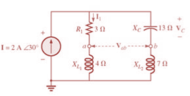
For the network in Fig. 17.43:
a. Find the current I1.
b. Calculate the voltage VC using the voltage divider rule.
c. Find the voltage Vab.
Expert Solution & Answer
Want to see the full answer?
Check out a sample textbook solution
Students have asked these similar questions
For an AM Radio channel, calculate the power efficiency of a system when the carrierroot-mean-square voltage is √20 V and the modulation index is 50%.
Calculate the frequency of the horizontal oscillator in a 819 line monochrome TV system, assuming that the power line frequency is 50Hz.
A planar LED is fabricated from gallium arsenide which has a refractive indexof 3.6.
Calculate the optical power emitted into air as a percentage of theinternal optical power for the device when the transmission factor at thecrystal–air interface is 0.68.
When the optical power generated internally is 50% of the electric powersupplied, determine the external power efficiency.
Chapter 17 Solutions
Introductory Circuit Analysis (13th Edition)
Ch. 17 - For theseries-parallel network in Fig.17.38. a....Ch. 17 - For the network in Fig. 17.39: a. Find the total...Ch. 17 - For the network in FIg. 17.40: a. Find the total...Ch. 17 - For the network in Fig. 17.41: a. Find the total...Ch. 17 - For the network in Fig. 17.42: a. Find the current...Ch. 17 - For the network in Fig. 17.43: a. Find the current...Ch. 17 - For the network in Fig. 17.44: a. Find the current...Ch. 17 - For the network in Fig. 17.45: a. Find the source...Ch. 17 - For the network of Fig. 17.46: a. Find the voltage...Ch. 17 - For the network in Fig. 17.47: a. Find the total...
Ch. 17 - For the network in Fig. 17.48: a. Find the total...Ch. 17 - For the network of Fig. 17.49: a. Find the total...Ch. 17 - For the network of Fig. 17.50: a. Find the total...Ch. 17 - Find the current I5 for the network in Fig. 17.51....Ch. 17 - Find the average power delivered to R5 in Fig....Ch. 17 - For the ladder network of Fig. 17.53: a. Find the...Ch. 17 - Prob. 17PCh. 17 - PSpice or Multisim For Problems 15 through 18, use...Ch. 17 - PSpice or Multisim For Problems 15 through 18, use...Ch. 17 - PSpice or Multisim For Problems 15 through 18, use...Ch. 17 - PSpice or Multisim For Problems 15 through 18, use...
Additional Engineering Textbook Solutions
Find more solutions based on key concepts
Identify the type of input and output configuration for each diff-amp in Figure 18-35.
Electronics Fundamentals: Circuits, Devices & Applications
How many coulombs do 93.8 1016 electrons represent?
Principles Of Electric Circuits
What is the color code for a 365- five-band precision resistor with a tolerance of 5 percent?
ELECTRICITY FOR TRADES (LOOSELEAF)
Three point charges of equal magnitude q, that will yield a zero net electric field at the origin.
Engineering Electromagnetics
Find I0 and I1 in the circuit in Fig.P2.12.
Basic Engineering Circuit Analysis
When travelers from the USA and Canada visit Europe, they encounter a different power distribution system. Wall...
Electric machinery fundamentals
Knowledge Booster


Learn more about
Need a deep-dive on the concept behind this application? Look no further. Learn more about this topic, electrical-engineering and related others by exploring similar questions and additional content below.Similar questions
- A transmission line has a characteristic impedance of ? = 21.05∠60.4 with propagation constant of 7.561 ? 10-3+ ? 0.002863 . Calculate the primary constants at an angular frequency of 5000 rad/sec.arrow_forwardAC Electricity: For the bridge network in Fig.18.88: a. Is the bridge balanced? b. Using mesh analysis, determine the current through the capacitive reactance.arrow_forwardIf the transmitter has a power of 8W (ignoring feedline losses and mismatch), find: the power delivered to the receiver (in dBm). Round off your answers into two decimal places.arrow_forward
- Q3 / A test signal ( sine wave 20kHz , 3V ) is used to modulate a carrier sinusoidal signal ( 1MHz , 7V ) using an AM - DSB LC system . calculate : ( a ) the total output power that would be delivered to the 550 antenna , ( b ) the USB power , ( c )transmission efficiencyarrow_forwardOn the antenna of a receiver, the following tank is observed: L: 55hp, C: variable trimer. a)If the station frequency is 1.2MHz. Determine: the value of the trimer if the quality factor is 250 b) calculate BWarrow_forwardGiven the voltage and current shown in Fig. 16.70, find the parallel network internal to the container. That is, find the actual value of each component using the provided frequency.arrow_forward
- In an AM transmission system the transmitter current was found to be 9.A. If the carrier signal is the only one to be sent and later increases to 10.72 A. Also if the carrier is modulated by a single sinusoidal wave, compute the percentage modulation. Again find the current of the antenna if the percentage of modulation changes 85%.arrow_forwardA telephone line having a bandwidth of 3 kHz is assigned for data communication. The SNR is 3050. What will be the capacity for the channel?arrow_forward1 (AM) An AM transmitter has a 1KW carrier power and is modulated by a sinusoidal tone. If you have 0.7 modulation index, what is the total power necessary for transmission?arrow_forward
- The ERP of a transmitting station is specified as 17W in a given direction. Express this as an EIRP in dBm.arrow_forwardDetermine the output voltage for the circuit of Fig. 11.52arrow_forwardWhich type of modulation is used for the following: a) Geostationary satellite broadcasting weather-related data. b) UHF in-car CB radio for 4wd drivers. c) Mobile internet services.arrow_forward
arrow_back_ios
SEE MORE QUESTIONS
arrow_forward_ios
Recommended textbooks for you
 Introductory Circuit Analysis (13th Edition)Electrical EngineeringISBN:9780133923605Author:Robert L. BoylestadPublisher:PEARSON
 Delmar's Standard Textbook Of ElectricityElectrical EngineeringISBN:9781337900348Author:Stephen L. HermanPublisher:Cengage Learning
 Programmable Logic ControllersElectrical EngineeringISBN:9780073373843Author:Frank D. PetruzellaPublisher:McGraw-Hill Education
 Fundamentals of Electric CircuitsElectrical EngineeringISBN:9780078028229Author:Charles K Alexander, Matthew SadikuPublisher:McGraw-Hill Education
 Electric Circuits. (11th Edition)Electrical EngineeringISBN:9780134746968Author:James W. Nilsson, Susan RiedelPublisher:PEARSON
 Engineering ElectromagneticsElectrical EngineeringISBN:9780078028151Author:Hayt, William H. (william Hart), Jr, BUCK, John A.Publisher:Mcgraw-hill Education,
Introductory Circuit Analysis (13th Edition)
Electrical Engineering
ISBN:9780133923605
Author:Robert L. Boylestad
Publisher:PEARSON
Delmar's Standard Textbook Of Electricity
Electrical Engineering
ISBN:9781337900348
Author:Stephen L. Herman
Publisher:Cengage Learning
Programmable Logic Controllers
Electrical Engineering
ISBN:9780073373843
Author:Frank D. Petruzella
Publisher:McGraw-Hill Education
Fundamentals of Electric Circuits
Electrical Engineering
ISBN:9780078028229
Author:Charles K Alexander, Matthew Sadiku
Publisher:McGraw-Hill Education
Electric Circuits. (11th Edition)
Electrical Engineering
ISBN:9780134746968
Author:James W. Nilsson, Susan Riedel
Publisher:PEARSON
Engineering Electromagnetics
Electrical Engineering
ISBN:9780078028151
Author:Hayt, William H. (william Hart), Jr, BUCK, John A.
Publisher:Mcgraw-hill Education,
Nodal Analysis for Circuits Explained; Author: Engineer4Free;https://www.youtube.com/watch?v=f-sbANgw4fo;License: Standard Youtube License