EBK DELMAR'S STANDARD TEXTBOOK OF ELECT
6th Edition
ISBN: 9781305537125
Author: Herman
Publisher: YUZU
expand_more
expand_more
format_list_bulleted
Concept explainers
Videos
Textbook Question
Chapter 19, Problem 6RQ
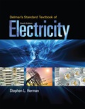
In the circuit shown in Figure 19−1, the resistor has a current flow of 6.5 A and the inductor has a current flow of 8 A. What is the total current in this circuti?
Expert Solution & Answer
Want to see the full answer?
Check out a sample textbook solution
Students have asked these similar questions
An RL series circuit is connected to a 240 volt 60 hz line the capacitor has current of 1.25 amperes flowling though it. the Xc of the inductor is 22 ohms. the resistor has a resistance of 16ohms. how much voltage is dropped across the resistor?
a capacitor and a resistor are connected in parellel to a 120 v 60 hz line the resistor has a resistance of 40 ohms and the capacitor has a capacitance of 132.6 uf what is the total current flow through the circuit. what is the impedence and the power factor and how many degrees out of phase are the current and voltage out phase with eachother.
Four 2H inductors are connected in parallel. What is the equivalent inductance?
Chapter 19 Solutions
EBK DELMAR'S STANDARD TEXTBOOK OF ELECT
Ch. 19 - 1. When an inductor and a resistor are connected...Ch. 19 - 2. An inductor and resistor are connected in...Ch. 19 - 3. What is the impedance of the circuit in...Ch. 19 - 4. What is the power factor of the circuit in...Ch. 19 - How many degrees out of phase are the current and...Ch. 19 - In the circuit shown in Figure 191, the resistor...Ch. 19 - 7. A resistor and an inductor are connected in...Ch. 19 - The R-L parallel circuit shown in Figure 191 has...Ch. 19 - The R-L parallel circuit shown in Figure 191 has...Ch. 19 - How many degrees out of phase are the total...
Ch. 19 - Incandescent lighting of 500 W is connected in...Ch. 19 - You are working on a residential heat pump. The...Ch. 19 - Prob. 1PPCh. 19 - Assume that the current flow through the resistor,...Ch. 19 - Assume that the circuit in Figure 18-1 has an...Ch. 19 - Prob. 4PPCh. 19 - In an R-L parallel circuit, R=240 and XL=360. Find...Ch. 19 - In an R-L parallel circuit, IT=0.25 amps, IR=0.125...Ch. 19 - In an R-L parallel circuit, ET=120 volts,...Ch. 19 - In an R-L parallel circuit, ET=48 volts, IT=0.25...Ch. 19 - In an R-L parallel circuit, ET=240 volts, R=560 R...Ch. 19 - In an R-L parallel circuit, ET=240 volts, R=560,...Ch. 19 - In an R-L parallel circuit, ET=208 volts, R=2.4k,...Ch. 19 - In an R-L parallel circuit, ET=480 volts, R=16,...Ch. 19 - In an R-L parallel circuit, IT=1.25 amps, R=1.2k,...Ch. 19 - In an R-L parallel circuit, true power =4.6 watts...Ch. 19 - An R-L parallel circuit is connected to 240 volts...Ch. 19 - An R-L parallel circuit has an applied voltage of...
Knowledge Booster


Learn more about
Need a deep-dive on the concept behind this application? Look no further. Learn more about this topic, electrical-engineering and related others by exploring similar questions and additional content below.Similar questions
- An R-L series circuit contains two resistors and two inductors. The resistors dissipate powers of 96 watts and 125 watts. The inductors have reactive powers of 100 VARs and 78 VARs. What is the power factor?arrow_forwardThe circuit in Figure 24-2 is connected to a 120-V, 60-Hz line. The resistor has a resistance of 36 , the inductor has an inductive reactance of 40 , and the capacitor has a capacitive reactance of 50 . ET120VITZVAPFERIRR36PELILXL40VARsLLECICXC50VARsCCarrow_forwardI am having trouble with this problem it might be the dot notation for the inductors but I am not entierly sure that is the only issue I am havingarrow_forward
- two inductors are in a series. one inductor has 5 mH and the other has 600 microH. what is the total inductance?arrow_forwardQUESTION 9 E-06, PC-02. Three inductors 5 mH, 15 mH and 25 mH are connected in series. What is the total inductance? 5 mH. 45mH. Without knowing the coupling factor the total inductance cannot be found. QUESTION 10 E-06, PC-05. An inductor is said to be saturated when? The current through it is zero. The current is at a maximum. It will no longer accept lines of flux.arrow_forwardPlease solve fast ,Have very less time. Do correctly . What is the total inductance in the circuit in Figure 13-1? A) 2600 uH B) 2100 mH C) 602 mH D) 800 mHarrow_forward
- A Resistor and an Inductor of negligible Resistance are connected in series to an AC Supply The PD across the Resistor is 18 V and the PD across the Inductor is 24 V Calculate the Supply Voltage and the Phase Angle between Voltage and Currentarrow_forwardİf the effective voltage value is 80 volts and the effective current value is 4A in the series RLC circuit in the figure, what is the capacitance of the capacitor?arrow_forward2. The total inductance for this circuit is mh. 5h L₂ 10 h 10 harrow_forward
- a resistor and and capacitor are connected in parallel to a 277 v 60 hz power source. the resistor has a value of 50 ohms and the capacitor has a value of 40 uf what is the circuit power factor.arrow_forwardAn RC series circuit is connected is connected to 120V, 60Hz power source. The resistor is 25 ohms and has a voltage drop of 65 volts. What is the capacitance of the capacitor in uf?arrow_forwardThe attached image shows a circuit with an AC voltage source, a resistor, inductor, and capacitor connected in series. The circuit has the following characteristics: Resistor resistance: 10 ohm Capacitor capacitance: 0.05 F Inductor inductance: 13 H Current Amplitude: 4 A Voltage amplitude across the source: 60 V Frequency at the source: 0.3 Hz Voltage amplitude across the resistor: 35 V Voltage amplitude across the capacitor: 37 V Voltage amplitude across the inductor: 80 V (a) Calculate the RMS voltages from the amplitudes above. From the RMS voltages across the capacitor, inductor and resistor, calculate the RMS voltage of the AC source. Hint: Vrms = V0/sqrt(2) Vrms = sqrt( (Vrms,R)2 + (Vrms, L - Vrms, C)2 ) (b) Calculate the RMS value of the current (c) Using the resistance, capacitance, inductance, and the frequency of the AC voltage, calculate the impedance Z. From this, and the previously measured value of Vrms, find the RMS value of the current in the circuit.arrow_forward
arrow_back_ios
SEE MORE QUESTIONS
arrow_forward_ios
Recommended textbooks for you
 Delmar's Standard Textbook Of ElectricityElectrical EngineeringISBN:9781337900348Author:Stephen L. HermanPublisher:Cengage Learning
Delmar's Standard Textbook Of Electricity
Electrical Engineering
ISBN:9781337900348
Author:Stephen L. Herman
Publisher:Cengage Learning
Current Divider Rule; Author: Neso Academy;https://www.youtube.com/watch?v=hRU1mKWUehY;License: Standard YouTube License, CC-BY