
Introductory Circuit Analysis
13th Edition
ISBN: 9780133923919
Author: Boylestad, Robert L.
Publisher: Pearson Education
expand_more
expand_more
format_list_bulleted
Videos
Textbook Question
Chapter 19, Problem 7P
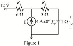
Using superposition, find the sinusoidal expression for the voltage Uc for the network of Fig. 19.111.
Expert Solution & Answer
Want to see the full answer?
Check out a sample textbook solution
Students have asked these similar questions
Using node analysis find v6
Assuning an autotransformer with a 70 percent tap and a supply voltage(vg) of 200 V,find the following parameters when a 3.6 kW load is connected across the secondary:
Find the Norton equivalent of the curcuit
Chapter 19 Solutions
Introductory Circuit Analysis
Ch. 19 - Using supeerposition, determine the current...Ch. 19 - Using superposition, determine the current through...Ch. 19 - Using superposition, determine the current IL for...Ch. 19 - Using superposition, determine the voltage across...Ch. 19 - Using superposition, determine the current through...Ch. 19 - Using superposition, find the sinusoidal...Ch. 19 - Using superposition, find the sinusoidal...Ch. 19 - Using superspostion, find the current I for the...Ch. 19 - Using superposition, determine the current IL...Ch. 19 - Using superposition, for the network of Fig....
Ch. 19 - Using superposition, determine the current IL for...Ch. 19 - Determine VL for the network of Fig. 19.116...Ch. 19 - Calculate the current I for the network of Fig....Ch. 19 - Find the voltage Vs for the network in Fig....Ch. 19 - Find the ThĂ©venin equivalent circuit for the...Ch. 19 - Find the Thevenin equivalent circuit for the...Ch. 19 - Find the Thevenin equivalent circuit for the...Ch. 19 - Find the Thevenin equivalent circuit for the...Ch. 19 - Find the Thevenin equivalent circuit for the...Ch. 19 - Find the Thevenin equivalent circuit for the...Ch. 19 - Find the ThĂªvenin equivalent circuit for the...Ch. 19 - Find the ThĂªvenin equivalent circuit for the...Ch. 19 - a. Find the ThĂ©venin equivalent circuit for the...Ch. 19 - a. Find the ThĂ©venin equivalent circuit for the...Ch. 19 - a. Find the ThĂ©venin equivalent circuit of the...Ch. 19 - Determine the ThĂ©venin equivalent circuit for the...Ch. 19 - Determine the ThĂ©venin equivalent circuit for the...Ch. 19 - Prob. 28PCh. 19 - Prob. 29PCh. 19 - Find the ThĂ©venin equivalent circuit for the...Ch. 19 - Determine the ThĂ©venin equivalent circuit for the...Ch. 19 - Prob. 32PCh. 19 - Find the ThĂ©venin equivalent circuit for the...Ch. 19 - Find the Norton equivalent circuit for the network...Ch. 19 - Find the Norton equivalent circuit for the network...Ch. 19 - Find the Norton equivalent circuit for the network...Ch. 19 - Find the Norton equivalent circuit for the portion...Ch. 19 - Find the Norton equivalent circuit for the portion...Ch. 19 - a. Find the Norton equivalent circuit for the...Ch. 19 - a. Find the Norton equivalent circuit for the...Ch. 19 - a. Find the Norton equivalent circuit for the...Ch. 19 - Determine the Norton equivalent circuit for the...Ch. 19 - Determine the Norton equivalent circuit for the...Ch. 19 - Find the Norton equivalent circuit for the network...Ch. 19 - Find the Norton equivalent circuit for the network...Ch. 19 - Prob. 46PCh. 19 - Prob. 47PCh. 19 - Find the load impedance ZL for the network of Fig....Ch. 19 - Find the load impedance ZL for the network of Fig....Ch. 19 - Find the load impedance ZL for the network of Fig....Ch. 19 - Find the load impedance ZL for the network of Fig....Ch. 19 - Prob. 52PCh. 19 - a. Determine the load impedance to replace the...Ch. 19 - a. Determine the load impedance to replace the...Ch. 19 - a. Determine the load impedance to replace the...Ch. 19 - Prob. 56PCh. 19 - a. For the network in Fig. 19.139, determine the...Ch. 19 - For the network in Fig. 19.140, determine two...Ch. 19 - Prob. 59PCh. 19 - Using Millmans theorem, determine the current...Ch. 19 - Prob. 61PCh. 19 - Determine the current IL for the network in Fig....Ch. 19 - Using schematics, determine V2 for the network in...Ch. 19 - Prob. 64PCh. 19 - Using schematics, plot the power to the R-C load...
Knowledge Booster


Learn more about
Need a deep-dive on the concept behind this application? Look no further. Learn more about this topic, electrical-engineering and related others by exploring similar questions and additional content below.Similar questions
- a) What is the use of Schering bridge in measurement system? b) Draw the schematic diagram of Anderson's bridge. c) Write down the balanced equations for Maxwell's bridge.arrow_forwardFind the ABCD constants of a network consisting of a 500-ohm resistor shunted across its sending end, a 1000 ohm resistor shunted across its receiving end and 100 ohms of resistance in series between the sending and receiving end.arrow_forwardUsing superposition, how can I determine the voltage across the capacitor C2 for the network of Fig. 19. 108.arrow_forward
- What should ZL be for the maximum power transfer in the circuit given below and calculate the maximum powerarrow_forwardFor the following ac networks, determine, using the superposition theorem, the indicated currentsarrow_forwardThe networks A and B in the circuit are reciprocal and symmetric. For network A, it is known that a′11=2 and a′12=1 Ω. Find the a parameters of network B.arrow_forward
- the following electrical circuit questions 1. Check the Reciprocity theorem for the network, with source and output response positions being at input and output terminals. 2.Draw an oriented graph for the network and obtain the corresponding incidence matrix. Then, find all cut sets and loops of the network. 3.For the network, assign arbitrary branch voltages and branch currents subject only to KVL and KCL constraints. Then, verify the conclusion of Tellegen’s theorem.arrow_forwardObtain the z parameters for the network in figure.arrow_forwardFind out the condition for reciprocity, symmetricity for chain parameters ABCD From the circuit given belowarrow_forward
- Find Y12 for the network shown in Fig.arrow_forwardQ.) Vo being the output voltage and Vi the input voltage, obtain the ABCD parameters of the circuit shown in the figure. If the source is connected to the left, obtain the output voltage.arrow_forwardDetermine the minimum number of wires in each conduit shown in Figure 1911. FIG. 1911arrow_forward
arrow_back_ios
SEE MORE QUESTIONS
arrow_forward_ios
Recommended textbooks for you

Introduction to Two-Port Networks; Author: ALL ABOUT ELECTRONICS;https://www.youtube.com/watch?v=ru2ItcD6unI;License: Standard Youtube License