
Concept explainers
Calculate the loads that is acting on the floor beam BE and girder AC.
Answer to Problem 1P
The uniformly distributed load acting on the floor beam BE is
The load acting at A, B, and C on the girder AC are
Explanation of Solution
Given information:
The building is a single-story building.
The building is subjected to uniformly distributed load of
Calculation:
Show the roof of the single-story storage building as shown in Figure 1.
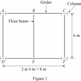
Refer Figure 1.
The columns are denoted by A, C, D, and F.
The floor beam is denoted by BE.
The girders are denoted by AC and DF.
Show the tributary area of the floor beam BE as shown in Figure 2.
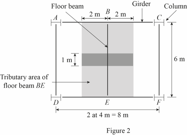
Refer Figure 2.
The tributary area of the floor beam BE is denoted by the shaded area.
Calculate the tributary area of the floor beam BE
The length of the floor beam BE is
Calculate the uniformly distributed load
Substitute
Show the uniformly distributed load acting on the floor beam BE as shown in Figure 3.
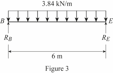
Refer Figure 3.
The reactions at B and E are denoted by
The loading on the floor beam BE is symmetrical.
Calculate the value of
Show the uniformly distributed load acting on the floor beam BE as shown in Figure 4.
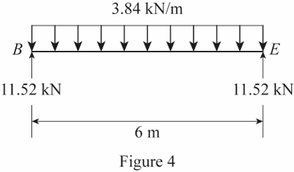
Refer Figure 4.
Thus, the uniformly distributed load acting on the floor beam BE is
Show the tributary area of the girder AC as shown in Figure 5.
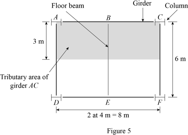
Refer Figure 5.
The tributary area of the girder AC is denoted by the shaded area.
Calculate the tributary area of the girder AC
Calculate the load
Substitute
The total load acting on the tributary area of the girder AC is
Almost half the load acts at the junction of the floor beam BE and the girder AC. Then,
The load acting at B is
The remaining half of the load acts equally on the column A and C. Then,
The load acting at A is
Show the load acting on the girder AC as shown in Figure 6.
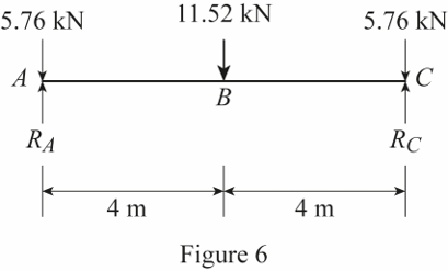
Refer Figure 6.
The reactions at A and C are denoted by
The loading on the girder AC is symmetrical.
Calculate the value of
Show the load acting on the girder AC as shown in Figure 7.
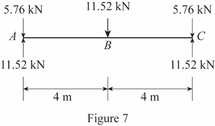
Refer Figure 7.
Thus, the load acting at A, B, and C on the girder AC are
Want to see more full solutions like this?
Chapter 2 Solutions
STRUCTURAL ANALYSIS (LL)


- Given. A two-story OCBF shown in Fig. 3.40c that forms part of the building frame system in SDC E. The axial loads on the ground floor brace B1 are as follows: Dead load D= 30 kips Live load L= 15 kips Seismic force QE = ±80 kips Snow load S= 0 kips Hydrostatic load H = 0 The redundancy coefficient p = 1.1. Mapped two-second såpectral acceleration, Sps = 0.826 g. Required. Determine a pipe section for brace B1, ASTM A53 Grade B steel; F, = 35 ksi, F = 60 ksi 16 ft 16 ft Figure -15 ft B2 B1 -- -15 ft B2 B1 Ordinary concentric brace frame (OCBF) example.arrow_forwardA doubly symmetrical I-section beam is reinforced by a flat plate attached to the upper flange as shown in Fig. P.10.3. If the resulting compound beam is subjected to a vertical shear load of 200 kN, determine the distribution of shear stress in the portion of the cross section that extends from the top of the plate to the ncutral axis. Calculate also the shcar force per unit length of bcam resisted by the shear connection between the plate and the flange of the I-section beam.arrow_forwardA channel-shaped beam with an overhanging end is loaded as shown in Fig. 7-46. The material is gray cast iron having an allowable working stress of 30 MPa in tension and 120 MPa in compression. Determine the maximum allowable value of P. Also compute the shearing stress developed in the beam loaded with P computed. P 2 cт 20 ст 2P cm 2 cm 12 cm 2 m 2 m- 1 m Fig. 7-46arrow_forward
- PROBLEM 3.5 -8arrow_forwardEXAMPLE 6-16 The beam shown in Fig. 6-29a has a cross-sectional area in the shape of a channel, Fig. 6-29b. Determine the maximum bending stress that occurs in the beam at section a-a. 2.6 kN 13/12 2 m (a) 1 m. y=59.09 mm N 15 mm- -250 mm- C 20 mm AT 200 mm -15 mmarrow_forwardThe floor of a building, shown in Fig. 2.6(a), is subjected to a uniformly distributed load of 3.5 kPa over its surface area.Determine the loads acting on all the members of the floor system.arrow_forward
- 4.19 and 4.20 Knowing that for the extruded beam shown the allowable stress is 120 MPa in tension and 150 MPa in compres- sion, determine the largest couple M that can be applied. 50 mm Fig. P4.19 MOLO 150 mm a hp 125 mm 125 mm M UE ■ R 80 mm 40 mm Fig. P4.20 M 54 mm ^ + 4)arrow_forwardA beam having a span of 4m is subjected to a maximum shear of 20 kN. It has a triangular cross - section having a base width of 140 mm and an altitude of 300 mm. Which of the following gives the maximum shearing stress developed on the beam? a. 1.43 MPa b. 1.80 MPa c. 1.62 MPa d. 1.78 MPaarrow_forwardA cantilever beam, 53 mm wide by 153 mm high and 6 m long, carries a load that varies uniformly fromzero at the free end to 1000 N/m at the wall. (a) Compute the magnitude and location of the maximumflexural stress. (b) Determine the type and magnitude of the stress in a fiber 20 mm from the top of thebeam at a section 2 m from the free end.arrow_forward
- A cantilever beam, 60 mm wide by 200 mm high and 6 m long carries load that varies uniformly from zero at the free end to 1000 N/m at the fixed end. a) Determine the maximum flexural stress. b) Determine the shearing stress develop in a fiber 40 mm from the top of the beam at a section 3 m from the free end. c) Determine the maximum shearing stress developed in the beam.arrow_forwardA cast iron beam is of T-section as shown in Fig. 7.21. The beam is şimply supported on a span of 8 m. The beam carries a uniformly distributed load of 1.5 kN/m length on the entire span. Determine the maximum tensile and maximum compressive stresses. 100 mm 20 mm 32.23 Fmm 80 mm 100 mm 67.77 mm 20 mm- Fig. 7.21arrow_forwardFind the required value of plastic moment capacity in the continuous beam shown in fig. The loads shown in fig are the collapse loadsarrow_forward
